Appendix B Cable Specifications
Alarm Port Pinouts
Alarm Port Pinouts
The router has four alarm inputs. The alarm setting is open or closed.
•Open means that the normal condition has current flowing through the contact (referred to as normally closed contact). The alarm is generated when the current stops.
•Closed means that no current flows through the contact (referred to as normally open contact). The alarm is generated when the current flows.
The alarm input is a
Note External DC bias is not required for the alarm port inputs.
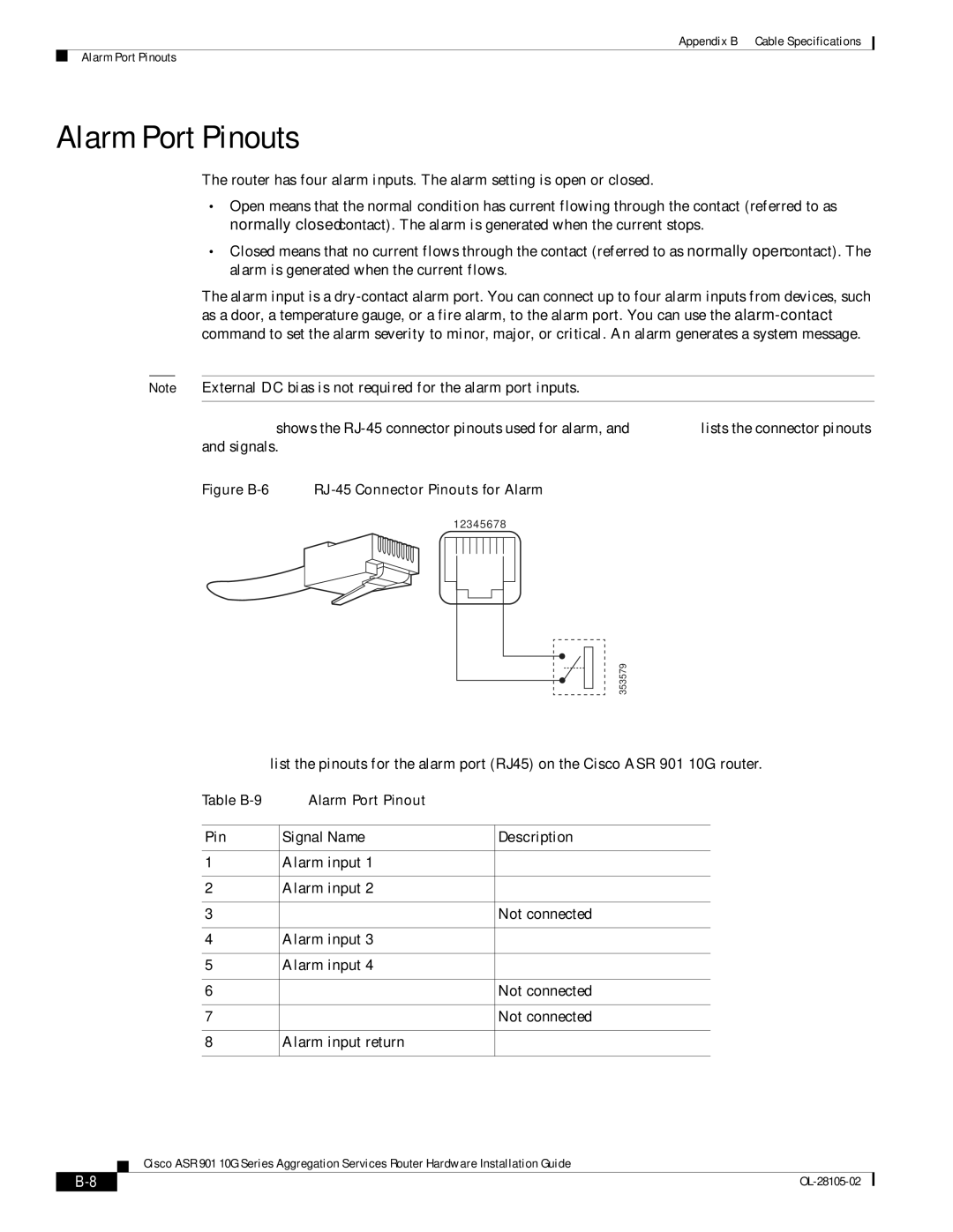
Figure B-6 shows the RJ-45 connector pinouts used for alarm, and Table B-9 lists the connector pinouts and signals.
Figure B-6 RJ-45 Connector Pinouts for Alarm
12345678
353579
Table
Table | Alarm Port Pinout |
|
|
|
|
Pin | Signal Name | Description |
|
|
|
1 | Alarm input 1 |
|
|
|
|
2 | Alarm input 2 |
|
|
|
|
3 |
| Not connected |
|
|
|
4 | Alarm input 3 |
|
|
|
|
5 | Alarm input 4 |
|
|
|
|
6 |
| Not connected |
|
|
|
7 |
| Not connected |
|
|
|
8 | Alarm input return |
|
|
|
|
Cisco ASR 901 10G Series Aggregation Services Router Hardware Installation Guide
|
|
| |
|
|