Installing and Removing Components
Installing and Removing a Blade Server
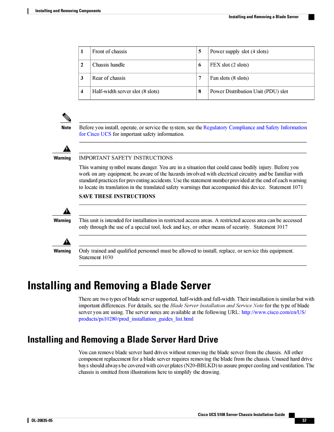
1 | Front of chassis | 5 | Power supply slot (4 slots) |
2 | Chassis handle | 6 | FEX slot (2 slots) |
3 | Rear of chassis | 7 | Fan slots (8 slots) |
4 | 8 | Power Distribution Unit (PDU) slot |
Note Before you install, operate, or service the system, see the Regulatory Compliance and Safety Information for Cisco UCS for important safety information.
Warning IMPORTANT SAFETY INSTRUCTIONS
This warning symbol means danger. You are in a situation that could cause bodily injury. Before you work on any equipment, be aware of the hazards involved with electrical circuitry and be familiar with standard practices for preventing accidents. Use the statement number provided at the end of each warning to locate its translation in the translated safety warnings that accompanied this device. Statement 1071
SAVE THESE INSTRUCTIONS
Warning This unit is intended for installation in restricted access areas. A restricted access area can be accessed only through the use of a special tool, lock and key, or other means of security. Statement 1017
Warning Only trained and qualified personnel must be allowed to install, replace, or service this equipment. Statement 1030
Installing and Removing a Blade Server
There are two types of blade server supported,
Installing and Removing a Blade Server Hard Drive
You can remove blade server hard drives without removing the blade server from the chassis. All other component replacement for a blade server requires removing the blade from the chassis. Unused hard drive bays should always be covered with cover plates
Cisco UCS 5108 Server Chassis Installation Guide
57 |
