Wireless-G Router for Mobile Broadband
Wall-Mount Option
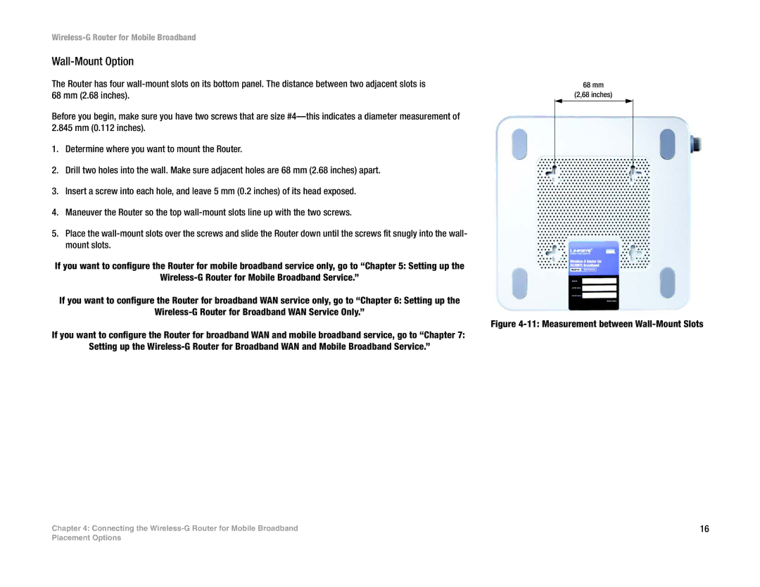
The Router has four
Before you begin, make sure you have two screws that are size
1.Determine where you want to mount the Router.
2.Drill two holes into the wall. Make sure adjacent holes are 68 mm (2.68 inches) apart.
3.Insert a screw into each hole, and leave 5 mm (0.2 inches) of its head exposed.
4.Maneuver the Router so the top
5.Place the
If you want to configure the Router for mobile broadband service only, go to “Chapter 5: Setting up the
If you want to configure the Router for broadband WAN service only, go to “Chapter 6: Setting up the
If you want to configure the Router for broadband WAN and mobile broadband service, go to “Chapter 7: Setting up the
Chapter 4: Connecting the Wireless-G Router for Mobile Broadband
68mm
(2,68 inches)
Figure 4-11: Measurement between Wall-Mount Slots
16
Placement Options