Maintenance and Service Guide
Page
Contents
Illustrated Parts Catalog
Screw Listing Index
Product Description
Key Description Options
Models
Key
Nafta
N16 100 Arabic 470024-098 Latin America
Compaq Notebook Evo N160 Models and Model Naming Conventions
Compaq Notebook Evo N160 Models and Model Naming Conventions
Compaq Notebook Evo N160 Models and Model Naming Conventions
Features
Maintenance and Service Guide
Clearing a Password
Power Management
Computer External Components
Front and Right Side Components
Front and Right Side Components
Component Function
Rear Panel and Left Side Components
Rear Panel and Left Side Components
Built-in microphone
Keyboard components are shown in -4 and described in Table
Keyboard Components
Fn key
Top Components
Top Components
Top Components
Bottom Components
Bottom Components
Bottom Components
Design Overview
Troubleshooting
Using the PhoenixBIOS Setup Utility
Section Description
Troubleshooting Flowcharts
Troubleshooting Flowcharts Overview
Initial Troubleshooting
Working?
No Power, Part
From Section No Power, Part
Internal Go to Section No Power Part
From Section No Power, Part Open Computer
No Video, Part
From Section No Video, Part Remove
Switch box
Nonfunctioning Docking Station if applicable
No Operating System OS Loading
No OS Loading from Hard Drive, Part
From Section
System Files on hard Drive? Install OS Reboot
No OS Loading from Diskette Drive
No OS Loading from CD- or DVD-ROM Drive
No Audio, Part
Undock
From Section No Audio, Part
Nonfunctioning Device
Nonfunctioning Keyboard
Nonfunctioning Pointing Device
Network or Modem Connection Problems
Illustrated Parts Catalog
Serial Number Location
Computer System Major Components
Computer System Major Components
Spare Parts Computer System Major Components
Spare Part
Description Number Display
Plastics and Hardware Kit, includes
Computer System Major Components
Mini PCI communications boards
System board
Sub I/O board
Hard drives
Computer System Major Components
Battery packs
Description Number Speakers
Base enclosure
Modular media bay device
Plastics and Hardware Kit Components
Plastics and Hardware Kit Components Spare Part Number
Description Number Hard drives
Mass Storage Devices
Mass Storage Devices
Miscellaneous
Spare Parts Miscellaneous not illustrated
Power cord, 2 wire
Power cord, 3 wire
External battery charger
Description Number AC adapters
Removal and Replacement Preliminaries
Tools Required
Plastic Parts
Service Considerations
Cables and Connectors
Preventing Damage to Removable Drives
Packaging and Transporting Precautions
Preventing Electrostatic Damage
Workstation Precautions
Grounding Equipment and Methods
Typical Electrostatic Voltage Levels
Static-Shielding Materials
Relative Humidity Event 10% 40% 55%
Material Use Voltage Protection Level
Removal and Replacement Procedures
Serial Number
Section Description # of Screws Removed
Disassembly Sequence Chart
Disassembly Sequence Chart
Preparing the Computer for Disassembly
Removing the Battery Pack
Reverse the above procedure to install the hard drive
Removing the Hard Drive from the Hard Drive Sleeve
Removing a Modular Media Bay Device
Memory Expansion Board
Removing the Memory Expansion Compartment Cover
Removing a Memory Expansion Board
Computer Feet
Replacing the Computer Feet
Switch Cover
Removing the Switch Cover Screws
Reverse the above procedure to install the switch cover
Keyboard
Keyboards Spare Part Number Information
11. Releasing the Keyboard
Maintenance and Service Guide
Fan Assembly
Fan Assembly Spare Part Number Information
Reverse the above procedure to install the fan assembly
Processor
Processors Spare Part Number Information
Reverse the above procedure to install the processor
Display
Displays Spare Part Number Information
15. Removing the Hinge Covers and Display Screws
16. Disconnecting the Display Cables
Reverse the above procedure to install the display
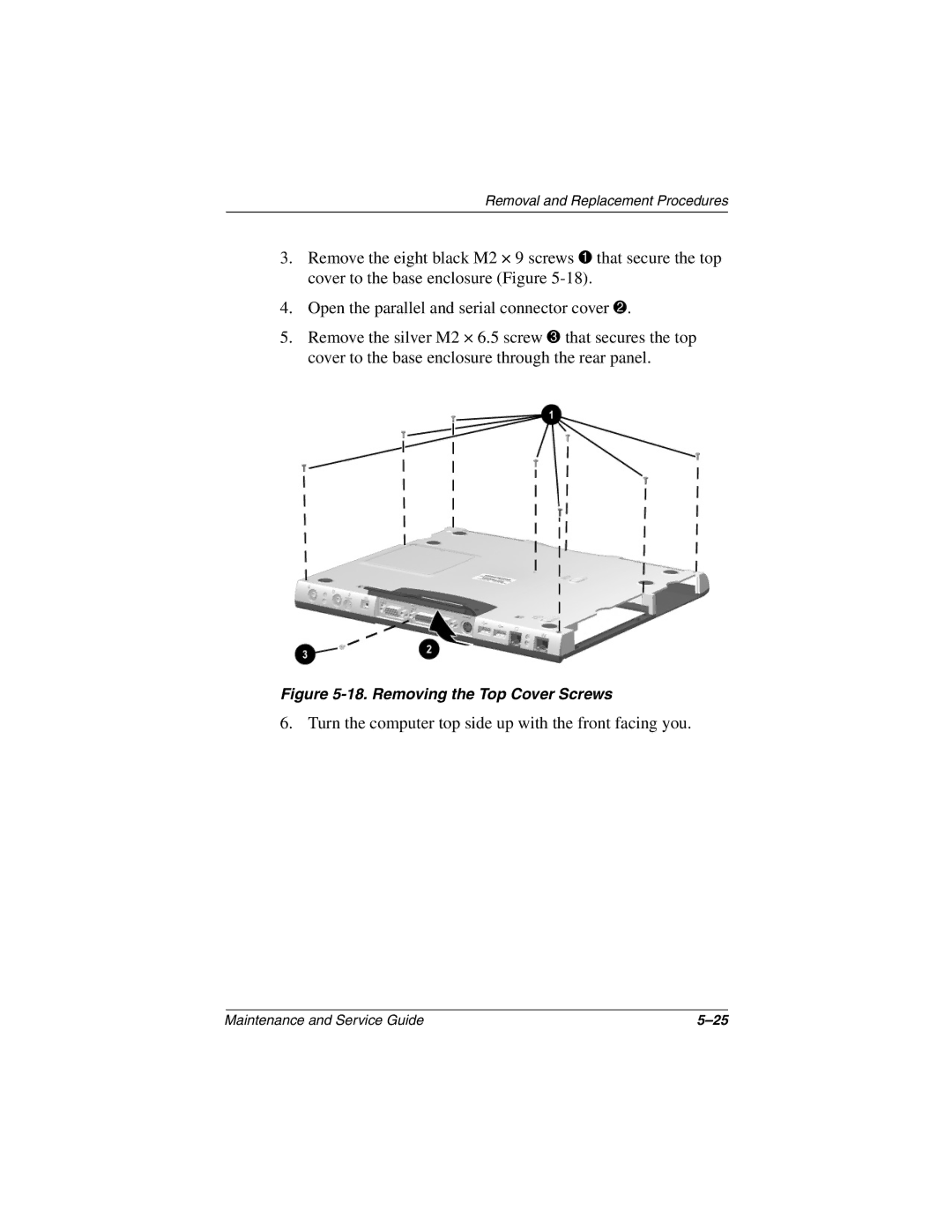
Top Cover
Top Cover Spare Part Number Information
Turn the computer top side up with the front facing you
Removal and Replacement Procedures
Lift the top cover straight up to remove it Figure
Speaker Assembly
Speaker Assembly Spare Part Number Information
21. Removing the Speaker Assemblies
Disk Cell RTC Battery
22. Removing the Disk Cell RTC Battery
Mini PCI Communications Board
Mini PCI Communications Boards Spare Part Number Information
23. Removing the Mini PCI Communications Board
Sub I/O board 251381-001
Sub I/O Board
Sub I/O Board Spare Part Number Information
24. Removing the Right Display Support
25. Removing the Sub I/O Board
System board 251368-001
System Board
System Board Spare Part Number Information
26. Removing the Hard Drive Bracket
27. Removing the Left Display Support and System Board Screw
28. Removing the System Board
Computer
Shock
Vibration
Inch XGA, TFT Display
Height 20.28 cm Depth 10.64 27.03 cm Width 13.3 33.79 cm
Hard Drives
30.0 GB 20.0 GB 15.0 GB Physical configuration
Buffer size3
Disk rotational speed rpm
Transfer rate
Diskette Drive
CD-ROM Drive
Audio output level
DVD-ROM Drive
Disk thickness Track pitch
Disk thickness
CD-RW Drive
Center hole diameter
Cell, Li ion Battery Pack
Power supply input
AC Adapter
Energy
System DMA
Hardware DMA System Function
System Interrupts
Hardware IRQ System Function
System I/O Addresses
16F Unused
VGA
System Memory Map
Size Memory Address System Function
Pin Signal
Table A-1 RJ-45 Network Interface
Table A-2 RJ-11 Modem
Table A-3 Universal Serial Bus
Table A-4 Video
Table A-5 Parallel
Table A-6 External Monitor
Pin Signal Audio out
Pin Signal Audio
Table A-7 Stereo Speaker/Headphone
Table A-8 Microphone
Conductor Power Cord Set
General Requirements
Country Accredited Agency Applicable Note Number
Conductor Power Cord Set Requirements
Country-Specific Requirements
Power Cord Set Requirements
Head Color Qty Length Thread Width
Where used
Table C-1 Phillips M3 × 8.0 Screw
Head
Color Qty Length Thread Width Black Where used
Table C-2 Phillips M3.0 × 4.0 Screw
Color Qty Length Thread Width Silver Where used
Table C-3 Phillips M2.0 × 5.0 Screw
Table C-3 Phillips M2.0 × 5.0 Screw
Table C-3 Phillips M2.0 × 5.0 Screw
Table C-4 Phillips M2.0 × 9.0 Screw
Table C-4 Phillips M2.0 × 9.0 Screw
Table C-4 Phillips M2.0 × 9.0 Screw
Table C-4 Phillips M2.0 × 9.0 Screw
Table C-4 Phillips M2.0 × 9.0 Screw
Color Qty Length Thread Width Silver 10.5 Where used
Table C-5 Phillips M2.0 × 10.5 Screw
Table C-5 Phillips M2.0 × 10.5 Screw
Color Qty Length Thread Width Black 12.0 mm Where used
Table C-6 Phillips M2.0 × 12.0 Screw
Table C-7 Phillips M2.0 × 6.5 Screw
Table C-7 Phillips M2.0 × 6.5 Screw
Table C-7 Phillips M2.0 × 6.5 Screw
Table C-7 Phillips M2.0 × 6.5 Screw
Color Qty Length Thread Width Gold Where used
Table C-8 Phillips M2.0 × 5.0 Screw
Maintenance and Service Guide
Index
Index-2
Index-3
Index-4
Pin assignments A-2 RJ-11 P55 adapter spare part
Index-6