Maintenance and Service Guide
October
Compaq Notebook Evo N160 Series
Document Part Number
Maintenance and Service Guide First Edition October
2 Troubleshooting
Contents
1 Product Description
5 Removal and Replacement Procedures
4 Removal and Replacement Preliminaries
3 Illustrated Parts Catalog
Contents
B Power Cord Set Requirements
6 Specifications A Connector Pin Assignments
Screw Listing Index
Figure 1-1. Compaq Notebook Evo N160
Product Description
Computer models are shown in Table1-1
Models
Compaq Notebook Evo N160 Models and Model Naming Conventions
Product Description
Compaq Notebook Evo N160
Maintenance and Service Guide
Models and Model Naming Conventions Continued
Product Description
Models and Model Naming Conventions Continued
Compaq Notebook Evo N160
Product Description
Compaq Notebook Evo N160
Maintenance and Service Guide
Models and Model Naming Conventions Continued
Product Description
Models and Model Naming Conventions Continued
Compaq Notebook Evo N160
Product Description
Compaq Notebook Evo N160
Maintenance and Service Guide
Models and Model Naming Conventions Continued
Product Description
1.1 Features
Parallel devices External monitor 1394 digital devices AC power
Connectors for RJ-45 network RJ-11 modem Universal Serial Bus S-Video
Maintenance and Service Guide
Stereo line out/headphone Mono microphone QuickDock Port Replicator
1.2 Clearing a Password
1.3 Power Management
Maintenance and Service Guide
1.4 Computer External Components
Figure 1-2. Front and Right Side Components
Product Description
Front and Right Side Components
Maintenance and Service Guide
Product Description
Component
Rear Panel and Left Side Components
Figure 1-3. Rear Panel and Left Side Components
Product Description
1-14
Rear Panel and Left Side Components Continued
Maintenance and Service Guide
Product Description
Figure 1-4. Keyboard Components
Maintenance and Service Guide
Product Description
1-16
Keyboard Components
Maintenance and Service Guide
Caps lock key
Fn key
Top Components
Figure 1-5. Top Components
Product Description
1-18
Top Components Continued
Maintenance and Service Guide
Product Description
Figure 1-6. Bottom Components
Maintenance and Service Guide
Bottom Components
Product Description
Bottom Components Continued
Maintenance and Service Guide
Product Description
1.5 Design Overview
Using the PhoenixBIOS Setup Utility
Troubleshooting
Troubleshooting Flowcharts Overview
Troubleshooting Flowcharts
Troubleshooting
Initial Troubleshooting
Power up in docking station?
2.2 No Power, Part
Done
in docking
Troubleshooting
2.3 No Power, Part
Maintenance and Service Guide
Visually check for debris in battery socket and clean if necessary
Troubleshooting
2.4 No Power, Part
in computer and at power source
Replace external AC adapter
Troubleshooting
2.5 No Power, Part
Maintenance and Service Guide
Loose or
2.6 No Video, Part
Troubleshooting
2.7 No Video, Part
Maintenance and Service Guide
Continued from Section No Video, Part Remove
Troubleshooting
2.8 Nonfunctioning Docking Station if applicable
Maintenance and Service Guide
Reseat power
Troubleshooting
2.9 No Operating System OS Loading
Maintenance and Service Guide
Check the setup utility for correct booting order
2.10 No OS Loading from Hard Drive, Part
Boot from diskette?
priority through the setup utility and reboot
2.11 No OS Loading from Hard Drive, Part
Virus
2.12 No OS Loading from Hard Drive, Part
on hard
sectors
2.13 No OS Loading from Diskette Drive
Troubleshooting
2.14 No OS Loading from CD- or DVD-ROM Drive
bootable disc
2-16
Troubleshooting
2.15 No Audio, Part
Maintenance and Service Guide
Troubleshooting
2.16 No Audio, Part
Load drivers and set configuration
2-18
Troubleshooting
2.17 Nonfunctioning Device
Maintenance and Service Guide
2-19
Troubleshooting
2.18 Nonfunctioning Keyboard
Maintenance and Service Guide
2-20
Troubleshooting
2.19 Nonfunctioning Pointing Device
Maintenance and Service Guide
2-21
Troubleshooting
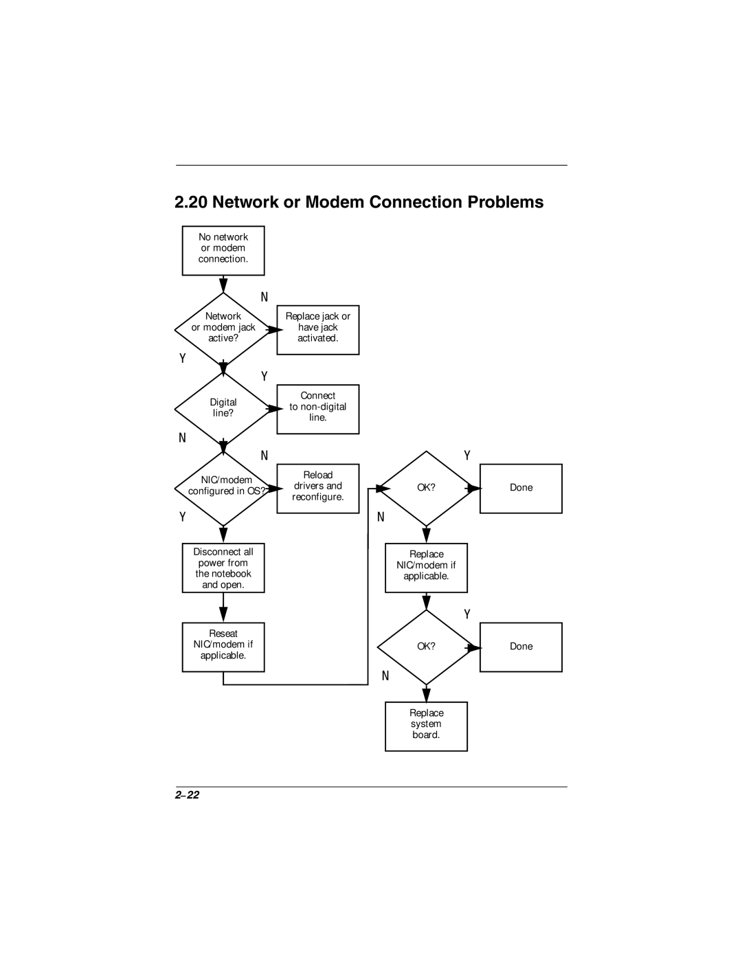
2.20 Network or Modem Connection Problems
Maintenance and Service Guide
reconfigure
3.1 Serial Number Location
Illustrated Parts Catalog
Maintenance and Service Guide
3.2 Computer System Major Components
Figure 3-2. Computer System Major Components
Illustrated Parts Catalog
Spare Parts Computer System Major Components
Maintenance and Service Guide
Illustrated Parts Catalog
Keyboard shield
Computer System Major Components continued
Maintenance and Service Guide
Illustrated Parts Catalog
Spare Parts Computer System Major Components Continued
Maintenance and Service Guide
Illustrated Parts Catalog
Computer System Major Components continued
Maintenance and Service Guide
Illustrated Parts Catalog
Spare Parts Computer System Major Components Continued
Maintenance and Service Guide
Illustrated Parts Catalog
Figure 3-3 Plastics and Hardware Kit Components
3.3 Plastics and Hardware Kit Components
Plastics and Hardware Kit Components Spare Part Number
Illustrated Parts Catalog
Maintenance and Service Guide
3.4 Mass Storage Devices
Figure 3-4. Mass Storage Devices
Mass Storage Devices
Spare Parts Miscellaneous not illustrated
3.5 Miscellaneous
Illustrated Parts Catalog
3-10
Spare Parts Miscellaneous not illustrated Continued
Maintenance and Service Guide
Illustrated Parts Catalog
4.1 Tools Required
Removal and Replacement Preliminaries
Cables and Connectors
4.2 Service Considerations
Plastic Parts
4.3 Preventing Damage to Removable Drives
4.4 Preventing Electrostatic Damage
4.5 Packaging and Transporting Precautions
4.6 Workstation Precautions
4.7 Grounding Equipment and Methods
Maintenance and Service Guide
Removal and Replacement Preliminaries
Nonconductive plastic bags, tubes, or boxes Metal tote boxes
Electrostatic voltage levels and protective materials
Removal and Replacement Procedures
5.1 Serial Number
Maintenance and Service Guide
Figure 5-1. Serial Number Location
Disassembly Sequence Chart
5.2 Disassembly Sequence Chart
Removal and Replacement Procedures
Maintenance and Service Guide
5.3 Preparing the Computer for Disassembly
Figure 5-3. Removing the Hard Drive
Figure 5-4. Removing the Hard Drive from the Hard Drive Sleeve
Figure 5-5. Removing a Modular Media Bay Device
5.4 Memory Expansion Board
Removal and Replacement Procedures
Reverse the above procedure to install a memory expansion board
Maintenance and Service Guide
7. The board tilts up at a 45-degree angle
Removal and Replacement Procedures
5.5 Computer Feet
Maintenance and Service Guide
Figure 5-8. Replacing the Computer Feet
Figure 5-9. Removing the Switch Cover Screws
5.6 Switch Cover
Reverse the above procedure to install the switch cover
8. Remove the switch cover
Figure 5-10. Removing the Switch Cover
Removal and Replacement Procedures
5.7 Keyboard
Maintenance and Service Guide
Keyboards Spare Part Number Information
Maintenance and Service Guide
Removal and Replacement Procedures
Figure 5-11. Releasing the Keyboard
5-14
5. Remove the keyboard shield
Fan Assembly Spare Part Number Information
5.8 Fan Assembly
Removal and Replacement Procedures
Maintenance and Service Guide
4. Disconnect the fan cable from the system board 1 Figure
a. Switch cover Section b. Keyboard and keyboard shield Section
5.9 Processor
c. Fan assembly Section
Removal and Replacement Procedures
3. Lift the processor straight up 2 to remove it from its socket
Removal and Replacement Procedures
5.10 Display
Maintenance and Service Guide
Displays Spare Part Number Information
7. Remove the hinge covers
9. Position the computer so the front faces you
15. Lift the display straight up to remove it
Top Cover Spare Part Number Information
5.11 Top Cover
4. Open the parallel and serial connector cover
7. Release the ZIF connector 1 to which the TouchPad cable is attached and disconnect the TouchPad cable 2 from the system board Figure
Removal and Replacement Procedures
Reverse the above procedure to install the top cover
Maintenance and Service Guide
9. Lift the top cover straight up to remove it Figure
Speaker Assembly Spare Part Number Information
5.12 Speaker Assembly
Removal and Replacement Procedures
Reverse the above procedure to install the speaker assemblies
Maintenance and Service Guide
2. Disconnect the speaker cables 1 from the system board Figure
Figure 5-22. Removing the Disk Cell RTC Battery
5.13 Disk Cell RTC Battery
Removal and Replacement Procedures
5.14 Mini PCI Communications Board
Maintenance and Service Guide
Mini PCI Communications Boards Spare Part Number Information
The board tilts up at a 45-degree angle
Removal and Replacement Procedures
5.15 Sub I/O Board
Maintenance and Service Guide
Sub I/O Board Spare Part Number Information
3. Remove the right display support
4. Disconnect the modem/NIC cable 1 from the sub I/O board Figure
Removal and Replacement Procedures
5.16 System Board
Maintenance and Service Guide
System Board Spare Part Number Information
3. Disconnect the speaker assembly cables 2 from the system board
7. Remove the left display support
9. Press in and hold the PC Card eject button 1 Figure
This chapter provides physical and performance specifications
Specifications
Maintenance and Service Guide
Computer
Computer Continued
Specifications
Shock
Vibration
Maintenance and Service Guide
Specifications
14.1-inch XGA, TFT Display
13.3-inch XGA, TFT Display
Specifications
Logical configuration
Specifications
Maintenance and Service Guide
Hard Drives
Physical configuration
Specifications
Hard Drives Continued
30.0 GB
Maintenance and Service Guide
Specifications
Diskette Drive
Diskette size
CD-ROM Drive
Specifications
Maintenance and Service Guide
Specifications
DVD-ROM Drive
CD-RW Drive
Specifications
6-10
Specifications
8-cell, Li ion Battery Pack
Maintenance and Service Guide
AC Adapter
System DMA
Specifications
Hardware DMA
System Function
Maintenance and Service Guide
Specifications
System Interrupts
System I/O Addresses
Specifications
6-14
Maintenance and Service Guide
Specifications
System I/O Addresses Continued
Specifications
6-16
Maintenance and Service Guide
Specifications
System Memory Map
Maintenance and Service Guide
Connector Pin Assignments
Table A-1 RJ-45 Network Interface
Table A-2 RJ-11 Modem
Connector Pin Assignments
Table A-3 Universal Serial Bus
Maintenance and Service Guide
Connector Pin Assignments
Table A-4 S-Video
Ground Y
Table A-5 Parallel
Connector Pin Assignments
Maintenance and Service Guide
Connector Pin Assignments
Table A-6 External Monitor
Table A-7 Stereo Speaker/Headphone
Connector Pin Assignments
Table A-8 Microphone
3-Conductor Power Cord Set
Power Cord Set Requirements
General Requirements
Country-Specific Requirements
Page
Maintenance and Service Guide
Screw Listing
Table C-1 Phillips M3 × 8.0 Screw
Table C-2 Phillips M3.0 × 4.0 Screw
Table C-3 Phillips M2.0 × 5.0 Screw
Maintenance and Service Guide
Table C-3 Phillips M2.0 × 5.0 Screw Continued
Maintenance and Service Guide
Table C-4 Phillips M2.0 × 9.0 Screw
Table C-4 Phillips M2.0 × 9.0 Screw Continued
Maintenance and Service Guide
Table C-4 Phillips M2.0 × 9.0 Screw Continued
Maintenance and Service Guide
C-10
Table C-4 Phillips M2.0 × 9.0 Screw Continued
Table C-5 Phillips M2.0 × 10.5 Screw
Maintenance and Service Guide
C-11
C-12
Table C-5 Phillips M2.0 × 10.5 Screw Continued
Table C-6 Phillips M2.0 × 12.0 Screw
Maintenance and Service Guide
C-13
C-14
Table C-7 Phillips M2.0 × 6.5 Screw
Table C-7 Phillips M2.0 × 6.5 Screw Continued
Maintenance and Service Guide
C-15
C-16
Table C-7 Phillips M2.0 × 6.5 Screw Continued
Maintenance and Service Guide
C-17
C-18
Table C-8 Phillips M2.0 × 5.0 Screw
C-19
Maintenance and Service Guide
Index
Index-2
Page
Page