Removal and Replacement Procedures
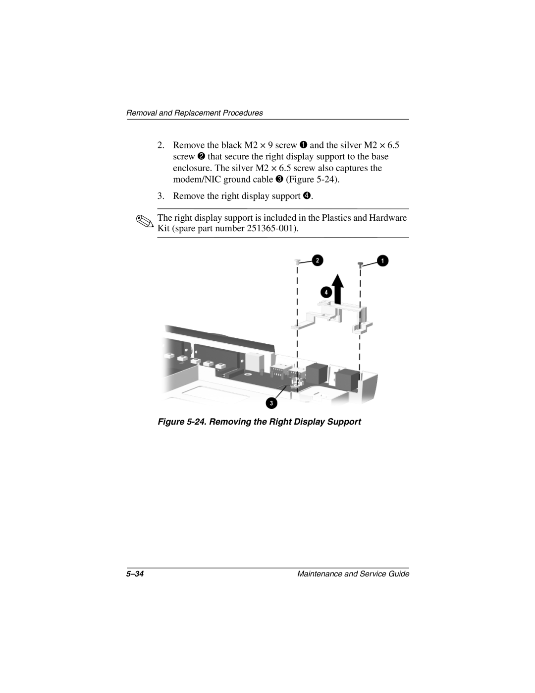
2.Remove the black M2 × 9 screw 1 and the silver M2 × 6.5 screw 2 that secure the right display support to the base enclosure. The silver M2 × 6.5 screw also captures the modem/NIC ground cable 3 (Figure
3.Remove the right display support 4.
✎The right display support is included in the Plastics and Hardware Kit (spare part number
Figure 5-24. Removing the Right Display Support
Maintenance and Service Guide |