|
|
| TRANSFRMR |
|
|
|
|
| WHEN |
|
|
| ||
|
|
|
|
|
|
|
| NOT |
|
|
| |||
|
|
|
|
|
|
|
|
|
|
| JUMPER |
|
|
|
|
|
|
| .AUTOFILL |
|
|
|
|
| USED |
|
|
| |
|
|
|
| CNTL |
|
| HPS/LPSHPS/LPSOPSOPS1TAS1TAS |
|
|
| ||||
| FROMFROMCOMPOPT | 1LS 1LS |
| L1 |
|
| ||||||||
2 | 1 | 2 | 3 | 3 | 4 | 4 | 11 | 11 | 13 | 13 | 14 | L2 | L3 | |
4 | 3 | 2 | 1 |
| 6 5 4 | 3 | 2 | 1 | 4 | 3 | 2 | 1 |
AC IN 4 | AC IN + 3 | AC OUT 2 | AC OUT + 1 | F1 | LLS/WPS LLS/WPS NOT USED | NOT USED | HPS/LPS | HPS/LPS | OPS | OPS | FSTAT | FSTAT |
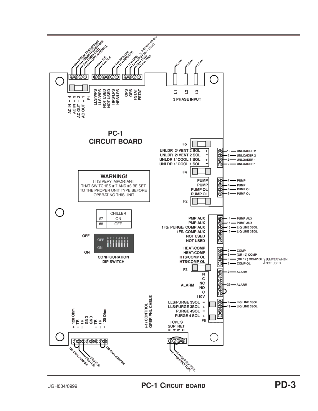
CIRCUIT BOARD
WARNING!
IT IS VERY IMPORTANT
THAT SWITCHES # 7 AND #8 BE SET TO THE PROPER UNIT TYPE BEFORE OPERATING THIS UNIT
|
|
| CHILLER | |||||
| #7 |
|
|
| ON |
|
| |
| #8 |
|
|
| OFF |
| ||
|
|
|
|
|
|
|
|
|
OFF | 7 | 6 | 5 | 4 | 3 | 2 1 | ||
8 | ||||||||
ON
CONFIGURATION
DIP SWITCH
L1 | L2 | L3 |
3 PHASE INPUT
F5
UNLDR 2/ VENT 2 SOL | + | ||||
UNLDR 2/ VENT 2 SOL |
|
|
| ||
|
|
| |||
UNLDR 1/ COOL 1 SOL | + | ||||
UNLDR 1/ COOL 1 SOL |
|
|
| ||
|
|
| |||
F4 |
|
|
|
|
|
|
|
|
|
| |
|
|
|
|
|
|
PUMP
PUMP
PUMP OL
PUMP OL
F2
PMP AUX
PMP AUX 1FS/ PURGE/ COMP AUX 1FS/ COMP AUX NOT USED NOT USED
HEAT/COMP
HEAT/COMP
HTS/COMP OL
HTS/COMP OL
410 UNLOADER 2
3 | 2 | UNLOADER 2 |
2 | 2 | UNLOADER 1 |
1 | 9 | UNLOADER 1 |
4 | 2 | PUMP |
3 | 6 | PUMP |
2 | 6 | PUMP OL |
1 | 5 | PUMP OL |
614 PUMP AUX
515 PUMP AUX
415 LIQ LINE 3SOL
316 LIQ LINE 3SOL
2
1
4 2 | COMP |
38 (OR 12) COMP
28 (OR 12 ) COMP OL
1 8 | COMP OL |
JUMPER WHEN NOT USED
F3
ALARM
N
C
NC
6 | 2 | ALARM |
5 |
|
|
4 |
|
|
3 | 22 | ALARM |
120 Ohm TR TR GND GND TR TR 120 Ohm | ||||
+ + | + |
|
| |
NO
C 110V
LLS/PURGE 3SOL |
|
|
|
|
|
| |
LLS/PURGE 3SOL | + | ||
PURGE 4SOL |
|
|
|
|
|
| |
PURGE 4 SOL | + | ||
TCPL'S | F6 | ||
|
|
| |
SUP RET |
|
|
|
Y R R Y |
|
|
|
2 |
1 |
42 LIQ LINE 3SOL
319 LIQ LINE 3SOL
2
1
| 1 2 3 4 5 6 7 8 |
| 1 2 3 4 |
120 | 120 |
| |
| Ohm |
| |
Ohm | Y R | ||
| JUMPER . . | JUMPER | SUPPLYSUPPLY |
| DB9DB9 |
|
|
| (4 (5 |
|
|
| 8) 9) |
| TCPLTCPL |
|
|
| |
UGH004/0999 |