REPLACING THE FREEZESTAT
![]() WARNING: Electrical shock hazard
WARNING: Electrical shock hazard
Before attempting maintenance of any kind, stop the unit and disconnect and lock out the main power supply.
The freezestat unit is a bulb and capillary thermostat. To replace the unit:
1 Shut down the chiller and disconnect the process fluid lines.
| 2 |
| Disconnect and lockout the power supply. | ||||
|
|
| Drain the tank |
|
|
|
|
| 3 |
|
|
|
|
| |
|
|
| of all fluid through |
|
|
|
|
|
|
| the drain valve in the |
|
|
|
|
|
|
| base of the tank. |
|
|
|
|
|
|
|
|
|
|
|
|
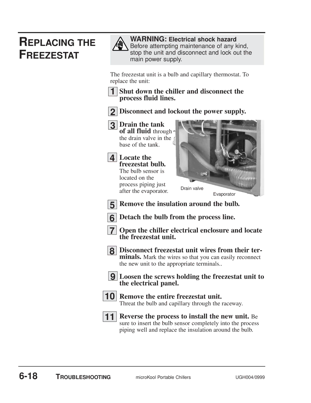
| 4 |
| Locate the |
|
|
|
|
|
|
| freezestat bulb. |
|
|
|
|
|
|
| The bulb sensor is |
|
|
|
|
|
|
| located on the |
|
|
|
|
|
|
| process piping just |
|
|
|
|
|
|
| Drain valve |
|
|
| |
|
|
| after the evaporator. |
|
|
| |
|
|
|
|
| Evaporator |
| |
|
|
|
|
|
|
| |
|
|
|
|
|
| ||
|
|
| Remove the insulation around the bulb. | ||||
| 5 |
| |||||
|
|
| Detach the bulb from the process line. | ||||
| 6 |
| |||||
|
|
|
|
|
|
| |
| 7 |
| Open the chiller electrical enclosure and locate | ||||
|
|
| the freezestat unit. |
|
|
|
|
|
|
| Disconnect freezestat unit wires from their ter- | ||||
| 8 |
| |||||
|
|
| minals. Mark the wires so that you can easily reconnect | ||||
|
|
| the new unit to the appropriate terminals.. | ||||
|
|
|
|
|
|
| |
| 9 |
| Loosen the screws holding the freezestat unit to | ||||
|
|
| the electrical panel. |
|
|
|
|
|
|
| |||||
10 |
| Remove the entire freezestat unit. | |||||
|
|
| Threat the bulb and capillary through the raceway. | ||||
|
|
| |||||
11 |
| Reverse the process to install the new unit. Be | |||||
|
|
| sure to insert the bulb sensor completely into the process | ||||
|
|
| piping well and replace the insulation around the bulb. | ||||
TROUBLESHOOTING | microKool Portable Chillers | UGH004/0999 |