Technical Specifications
Standard Cable Pinouts
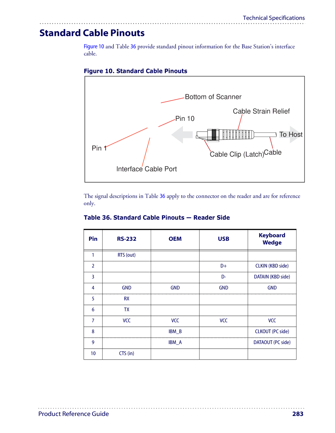
Figure 10 and Table 36 provide standard pinout information for the Base Station’s interface cable.
Figure 10. Standard Cable Pinouts
Bottom of Scanner
Cable Strain Relief
Pin 10 |
|
| To Host |
Pin 1 | Cable |
Cable Clip (Latch) | |
Interface Cable Port |
|
The signal descriptions in Table 36 apply to the connector on the reader and are for reference only.
Table 36. Standard Cable Pinouts — Reader Side
Pin | OEM | USB | Keyboard | ||
Wedge | |||||
|
|
|
| ||
|
|
|
|
| |
|
|
|
|
| |
1 | RTS (out) |
|
|
| |
|
|
|
|
| |
2 |
|
| D+ | CLKIN (KBD side) | |
|
|
|
|
| |
3 |
|
| D- | DATAIN (KBD side) | |
|
|
|
|
| |
4 | GND | GND | GND | GND | |
|
|
|
|
| |
5 | RX |
|
|
| |
|
|
|
|
| |
6 | TX |
|
|
| |
|
|
|
|
| |
7 | VCC | VCC | VCC | VCC | |
|
|
|
|
| |
8 |
| IBM_B |
| CLKOUT (PC side) | |
|
|
|
|
| |
9 |
| IBM_A |
| DATAOUT (PC side) | |
|
|
|
|
| |
10 | CTS (in) |
|
|
| |
|
|
|
|
|
Product Reference Guide | 283 |