Dell Vostro
W . d e l l . c o m s u p p o r t . d e l l . c o m
July DX333
Contents
Power Options Properties
Configuring for RAID Using the Intel Matrix
Connecting to a Network Adapter
Setting Up Your Internet Connection
Media Card Reader Problems
Sound and Speaker Problems
No sound from headphones Contents
Windows operating system Solid blue screen appears
Video and Monitor Problems
Dell Diagnostics Main Menu
If the screen is difficult to read
100
101
Replacing the Power Supply 152
Installing the Processor Fan/Heat Sink
150
151
189
207
Contents
Your system
What Are You Looking For? Find it Here Warranty information
Finding Information
Use the Service Tag to identify your
Computer when you use
Enter the Express Service Code to
Direct your call when contacting
Updates appropriate for your
Configuration
Education customers can also use
Other Dell customers
Windows Vista, click Windows Vista Start button
Problem
Icon
Setting Up and Using Your Computer
Front View of the Computer
Can contain an optional optical drive
Optional CD/DVD eject
Power button
Power light Light in the center of this button indicates
For more information
Perform an operating system shutdown
Back View of the Computer
Access to the inside of the computer. To use
Allow you to secure the computer cover to
Chassis with a padlock to prevent unauthorized
Padlock rings, insert a commercially available
Back Panel Connectors
Extremely low bass extension. Systems not using
Speakers in the surround sound setup
Connector is on the card
Speakers with integrated amplifiers
Installing Your Computer in an Enclosure
Setting Up and Using Your Computer
Connecting a USB Printer
Setting Up a Printer
Printer Cable
Page
Playing CDs and DVDs
Adjusting the Picture
Adjusting the Volume
DVD player includes the following basic buttons
Copying CDs and DVDs
Setting Up and Using Your Computer
Yes
Media Type Read Write Rewritable
Maybe
Using a Media Card Reader Optional
SecureDigital Card SD/ MultiMediaCard MMC
Connecting Two Monitors
Connecting Two Monitors With VGA Connectors
TV-OUT connector
Connecting a TV
May not be present on your computer Optional DVI adapter
Changing the Display Settings
Power Management Options in Windows XP
Standby Mode
Hibernate Mode
Power Options Properties
Power Management Options in Windows Vista
Standby Mode
Power Plan Properties
Enabling SpeedStep Technology
About RAID Configurations
RAID Level 1 Configuration
Configuring Your Hard Drives for RAID
Configuring for RAID Using the Intel Option ROM Utility
Configuring for RAID Using the Intel Matrix Storage Manager
Setting Up and Using Your Computer
Page
Setting Up and Using Your Computer
Transferring Information to a New Computer
Setting Up and Using Your Computer
Setting Up and Using Your Computer
Setting Up and Using Your Computer
Setting Up a Home and Office Network
Connecting to a Network Adapter
Network Setup Wizard
Network adapter connector
Connecting to the Internet
Setting Up Your Internet Connection
Setting Up and Using Your Computer
Setting Up and Using Your Computer
Troubleshooting Tips
Battery Problems
Follow these tips when you troubleshoot your computer
Solving Problems
Drive Problems
E C K T H E C a B L E C O N N E C T I O N S
Optical drive problems
Problems writing to a CD/DVD-RW drive
Mail, Modem, and Internet Problems
Hard drive problems
N T H E M O D E M D I a G N O S T I C S to O L
Solving Problems
Error Messages
Do not use these characters in filenames
Keyboard Problems
Lockups and Software Problems
Computer does not start up
Computer stops responding
Program stops responding
Solid blue screen appears
Windows XP
Other software problems
C K U P Y O U R F I L E S I M M E D I a T E L Y
Media Card Reader Problems
Memory Problems
Run the Dell Diagnostics see Dell Diagnostics on
Mouse Problems
Network Problems
Power Problems
Printer Problems
Scanner Problems
Sound and Speaker Problems
No sound from speakers
No sound from headphones
Video and Monitor Problems
If the screen is blank
If the screen is difficult to read
Power Lights
Troubleshooting Tools
Beep Codes
Code Description Suggested Remedy Repetitive Short Beeps
System Messages
Troubleshooting Tools
When to Use the Dell Diagnostics
Dell Diagnostics
Starting the Dell Diagnostics From Your Hard Drive
Dell Diagnostics Main Menu
Option Function
Option Function
Drivers
What Is a Driver?
Tab Function
Reinstalling Drivers and Utilities
Identifying Drivers
Troubleshooting Tools
Troubleshooting Tools
Restoring Your Operating System
Using Microsoft Windows System Restore
Using Dell PC Restore and Dell Factory Image Restore
Troubleshooting Tools
Troubleshooting Tools
Using the Operating System Media
Before you Begin
To reinstall Windows, you need the following items
Troubleshooting Software and Hardware Problems
Before You Begin
Removing and Installing Parts
Recommended Tools
Turning Off Your Computer
Before Working Inside Your Computer
Removing the Computer Cover
103
Computer cover
Inside View of Your Computer
Optical drive Power supply
105
Memory module Connector DIMM2 Connector DIMM3
Battery socket
System Board Components
106
107
DC Power Connector P1 13 14 15 16 17 18 19 20 21 22 23
Power Supply DC Connector Pin Assignments
108
109
110
DC Power Connector P7 Pin Number Signal Name
Memory
111
+12 Vadc Yellow
Memory Installation Guidelines
112
Memory connector DIMM1
Installing Memory
113
Cutouts
Notch Crossbar
Removing Memory
Cards
115
PCI and PCI Express Cards
117
Card retention bracket
118
Alignment bar Fully-seated card Not fully-seated card
PCI Express x16 card Securing tab
119
PCI Express x1 card slot PCI Express x16 card slot
Screw
Alignment guide Filler bracket
Guide notch
To Off
121
122
If you removed an add-in network connector
Bezel
Removing the Bezel
To On
Bezel grip
Clamp insert Back of computer
Replacing the Bezel
Align and insert the bezel clamps in the bezel insert
125
Clamp insert Back side of computer
Drives
126
Connecting Drive Cables
Drive Interface Connectors
Power cable
Recommended Drive Cable Connections
Hard Drives
Connecting and Disconnecting Drive Cables
Interface cable
129
Hard drive Power cable
Screws
Removing and Installing Parts
131
Connector Drive bay
System board Screws
Removing and Installing Parts
133
Second hard drive Power cable
Optional System board Screws
Floppy Drive
135
Removing and Installing Parts
Connector Floppy drive
137
Removing and Installing Parts
139
Drive panel insert optional
Media Card Reader
Media Card Reader Data cable Power cable
140
141
Connector FlexBay slot
Optical Drive
143
144
145
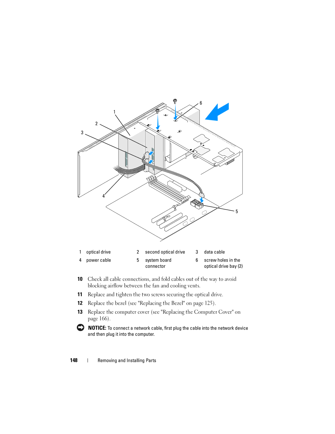
System board Screw holes Screws Connector Optical drive bay
Optical drive Data cable
147
Screw holes
149
Battery
Replacing the Battery
Battery release lever
Power Supply
151
Replacing the Power Supply
152
Panel
153
154
Removing the I/O Panel
Panel clamp Screw Cables
Processor Fan
Installing the I/O Panel
155
Removing the Processor Fan/Heat Sink Assembly
Assembly
156
Captive screws
Installing the Processor Fan/Heat Sink Assembly
157
Removing the Processor
Processor
158
159
Installing the Processor
Processor cover Socket
Removing and Installing Parts
161
Removing the Chassis Fan
Chassis Fan
162
Replacing the Chassis Fan
163
System Board
Removing the System Board
System Board Screws
Installing the System Board
165
Replacing the Computer Cover
167
Move the computer to the upright position
Computer cover tab Slot
168
Specifications
169
Integrated network interface capable of 10/100
Communication
170
171
172
173
Entering System Setup
System Setup
Overview
175
System Setup Options
176
FIXED, Dvmt Dvmt by default
Off On On by default
177
Boot Sequence
179
Clearing Forgotten Passwords
Clearing Cmos Settings
181
Cleaning Your Computer
Flashing the Bios
182
Mouse
Computer, Keyboard, and Monitor
183
Dell Technical Support Policy U.S. Only
CDs and DVDs
Definition of Dell-Installed Software and Peripherals
FCC Notice U.S. Only
Definition of Third-Party Software and Peripherals
FCC Class B
186
Product name Dell Vostro Model number
Company name Dell Inc
One Dell Way
Contacting Dell
187
188
Glossary
Glossary
190
191
192
193
194
195
196
197
198
199
200
201
202
203
204
205
206
Inside view, 105 stops responding
Index
Index
209
Problems battery, 59 beep codes
210
211
Booting to devices Using Windows Device Driver Rollback 212
USB
Wizard, 68 reinstalling, 94 scanner, 77 System Restore
213
214