Table
Pin No Function
6TxRx 3-
7TxRx 4+
8TxRx 4-
SFP Ports
The PowerConnect 2824 switch supports two SFP transceivers combo ports, and the PowerConnect 2848 switch supports four SFP transceivers combo ports for various
PowerConnect 2824 switch supports SFP diagnostics. The optical transceiver provides access to a set of parameters that can be monitored and displayed to the system administrator.
NOTE: If both
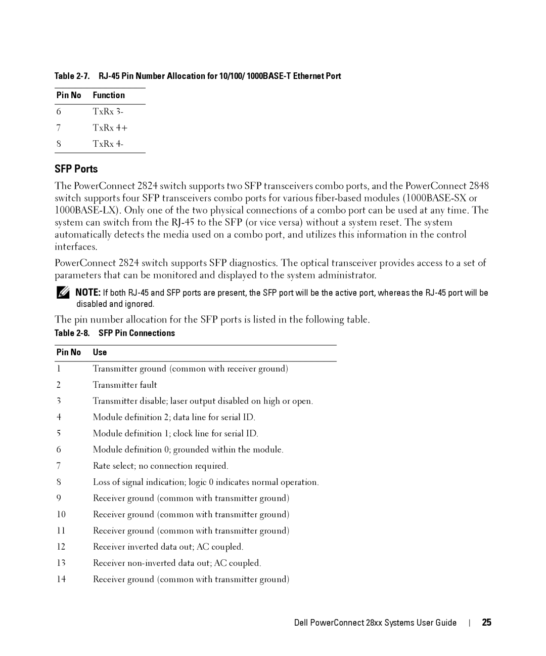
The pin number allocation for the SFP ports is listed in the following table.
Table 2-8. SFP Pin Connections
Pin No Use
1Transmitter ground (common with receiver ground)
2Transmitter fault
3Transmitter disable; laser output disabled on high or open.
4Module definition 2; data line for serial ID.
5Module definition 1; clock line for serial ID.
6Module definition 0; grounded within the module.
7Rate select; no connection required.
8Loss of signal indication; logic 0 indicates normal operation.
9Receiver ground (common with transmitter ground)
10Receiver ground (common with transmitter ground)
11Receiver ground (common with transmitter ground)
12Receiver inverted data out; AC coupled.
13Receiver
14Receiver ground (common with transmitter ground)
Dell PowerConnect 28xx Systems User Guide
25
