Page
Page
Contents
Logging in to CMC
Updating Firmware
Racadm
Configuring CMC
Viewing and Modifying CMC Network LAN Settings
Configuring Servers
Configuring CMC For Single Sign-On Or Smart Card Login 144
Configuring CMC To Send Alerts 114
Configuring User Accounts and Privileges 119
Configuring CMC to Use Command Line Consoles 149
Using FlexAddress and FlexAdress Plus Cards 160
Managing and Monitoring Power
Managing Fabrics
Managing Chassis Storage 191
Managing PCIe Slots 201
Frequently Asked Questions 226
Troubleshooting and Recovery 205
Using LCD Panel Interface 217
227
228
229
231
Overview
Management Features
What Is New In This Release
Key Features
Security Features
Chassis Overview
PSU
Drive enclosure
Supported Remote Access Connections
Minimum CMC Version
Supported Platforms
Supported Web Browsers
Managing Licenses
Types of Licenses
Acquiring Licenses
License Operations
Licensable Features in CMC
Managing Licenses Using CMC Web Interface
Managing Licenses Using Racadm
SSH
WS-MAN
Snmp
Viewing Localized Versions of the CMC Web Interface
Other Documents You May Need
Accessing documents from Dell support site
Page
Installing and Setting Up CMC
Installing CMC Hardware
Checklist To Set up Chassis
Before You Begin
Basic CMC Network Connection
Installing Remote Access Software on a Management Station
Installing Racadm on a Linux Management Station
Configuring a Web Browser
Uninstalling Racadm From a Linux Management Station
Proxy Server
Internet Explorer
Microsoft Phishing Filter
Certificate Revocation List CRL Fetching
Downloading Files From CMC With Internet Explorer
Mozilla FireFox
Enabling Animations In Internet Explorer
Setting Up Initial Access to CMC
Configuring Initial CMC Network
Configuring CMC Network Using LCD Panel Interface
Configure CMC?
Page
Apply settings to installed servers?
Auto-Apply settings to newly-inserted servers?
Dhcp
IPs will auto-increment by slot number
Interfaces and Protocols to Access CMC
Apply All Enclosure Settings?
Telnet console using an encrypted transport layer for higher
Setting Chassis Physical Location and Chassis Name
Setting Date and Time on CMC
Launching CMC Using Other Systems Management Tools
Downloading and Updating CMC Firmware
Configuring LEDs to Identify Components on the Chassis
Setting Date and Time on CMC Using CMC Web Interface
Setting Date and Time on CMC Using Racadm
Configuring LED Blinking Using CMC Web Interface
Cmc-active
Configuring CMC Properties
Configuring iDRAC Launch Method Using CMC Web Interface
Configuring Login Lockout Policy Attributes Using
Understanding Redundant CMC Environment
Active CMC Election Process
CMC Failsafe Mode
About Standby CMC
Configuring Front Panel
Configuring Power Button
Configuring LCD
Accessing a Server Using KVM
Mapping a Server to a DVD Drive
Mapping a Server to KVM Using CMC Web Interface
Mapping the Server to KVM Using LCD
Accessing CMC Web Interface
Logging in to CMC
Logging in to CMC Using a Smart Card
Logging in to CMC Using Single Sign-on
Logging In To CMC Using Serial, Telnet, Or SSH Console
Accessing CMC Using Racadm
Logging in to CMC Using Public Key Authentication
Multiple CMC Sessions
Changing Default Login Password
Changing Default Login Password Using Web Interface
Enabling or Disabling Default Password Warning Message
Changing Default Login Password Using Racadm
Viewing Currently Installed Firmware Versions
Bios
Updating Firmware
Downloading CMC Firmware
Viewing Currently Installed Firmware Versions Using Racadm
Updating the CMC Firmware
Updating CMC Firmware Using Web Interface
Signed CMC Firmware Image
Updating CMC Firmware Using Racadm
Updating Chassis Infrastructure Firmware
Updating Server iDRAC Firmware
Updating Chassis Infrastructure Firmware Using Racadm
Updating Server iDRAC Firmware Using Web Interface
Updating Server Component Firmware
Interface
Server Component Update Sequence
Lifecycle Controller may not be enabled
Bios NIC RAID
Enabling Lifecycle Controller
Filtering Components for Firmware Updates
Racadm getversion -l -m module -f filter
Filtering Components for Firmware Updates Using Racadm
Viewing Firmware Inventory
Viewing Firmware Inventory Using CMC Web Interface
Viewing Firmware Inventory Using Racadm
Saving Chassis Inventory Report Using CMC Web Interface
Configuring Network Share Using CMC Web Interface
Lifecycle Controller Job Operations
Rolling Back Server Component Firmware
Reinstalling Server Component Firmware
Re-installing Server Component Firmware Using Web Interface
Upgrading Server Component Firmware
Server Component Single Click Update Using Network Share
Pre-requisites for Using Network Share Update Mode
Deleting Scheduled Server Component Firmware Jobs
Updating Storage Component Using CMC Web Interface
Recovering iDRAC Firmware Using CMC
Viewing Chassis and Component Summaries
Chassis Graphics
Selected Component Information
Cpld
For Power Off
Viewing Server Model Name and Service Tag
Viewing Chassis Summary
Viewing Chassis Controller Information and Status
Viewing Information and Health Status of All Servers
Viewing Health Status and Information for Individual Server
Viewing Information and Health Status of the IOM
Viewing Information and Health Status of Fans
Racadm fanoffset -s offlowmediumhigh
Configuring Fans
Fan number is less than the lower critical threshold
Viewing Front Panel Properties
Viewing KVM Information and Health Status
Viewing LCD Information and Health
Page
Configuring CMC
Viewing and Modifying CMC Network LAN Settings
Viewing and Modifying CMC Network LAN Settings Using Racadm
Racadm config -g cfgLanNetworking -o cfgNicIPv4Enable
Racadm config -g cfgIpv6LanNetworking -o cfgIPv6Enable
Enabling the CMC Network Interface
Racadm config -g cfgLanNetworking -o cfgDNSServersFromDHCP
Enabling or Disabling Dhcp for DNS IP Addresses
Setting Static DNS IP addresses
Configuring DNS Settings IPv4 and IPv6
Racadm config -g cfgLanNetworking -o cfgDNSRegisterRac
Racadm config -g cfgLanNetworking -o cfgDNSRacName name
Configuring CMC Network and Login Security Settings
Setting the Maximum Transmission Unit MTU IPv4 and IPv6
Configuring IP Range Attributes Using CMC Web Interface
Racadm config -g cfgNetTuning -o cfgNetTuningNicSpeed speed
Configuring Virtual LAN Tag Properties for CMC Using Racadm
Configuring Virtual LAN Tag Properties for CMC
Configuring IP Range Attributes Using Racadm
Configuring Services
Racadm config -g cfgLanNetworking -o cfgNicVLanPriority
Racadm setniccfg -v Vlan id Vlan priority
Racadm setniccfg -v 1
CfgRacTuning CfgRacTuneRemoteRacadmEnable
Configuring Services Using CMC Web Interface
Configuring Services Using Racadm
Configuring CMC Extended Storage Card
Setting Up Chassis Group
Adding Members To Chassis Group
Removing a Member from the Leader
Disabling an Individual Member at the Member Chassis
Accessing the Web page of a Member Chassis or Server
Disbanding a Chassis Group
Saving Server Inventory Report
Propagating Leader Chassis Properties to Member Chassis
Server Inventory for MCM group
1PB8VF1
Exported Data
SLOT-01
Viewing Selected Chassis Inventory Using Web Interface
Chassis Group Inventory and Firmware Version
Viewing Chassis Group Inventory
Data Format
Configuring Multiple CMCs Using Racadm
Creating a CMC Configuration File
Parsing Rules
Racadm getconfig -g groupname -i index
CfgUserAdmin cfgUserAdminUserName= Username
Command, racadm getconfig -f myfile.cfg
Modifying the CMC IP Address
Viewing and Ending CMC Sessions
Viewing and Ending CMC Sessions Using Web Interface
Viewing and Ending CMC Sessions Using Racadm
Drac
Configuring Servers
Configuring Slot Names
Configuring iDRAC Network Settings
Configuring iDRAC QuickDeploy Network Settings
Page
Address range is not fully within
QuickDeploy Subnet error message is
Is 255.255.255.0 , the QuickDeploy IP
Assigning QuickDeploy IP Address to Servers
Modifying iDRAC Network Settings Using Racadm
CfgLanNetworking CfgIPv6LanNetworking CfgRacTuning
Configuring iDRAC Virtual LAN Tag Settings
Configuring iDRAC Virtual LAN Tag Settings Using Racadm
CfgRemoteHosts CfgSerial CfgSessionManagement
Racadm setniccfg -m server-1 -v 1
CD/DVD
Setting First Boot Device
PXE
Setting First Boot Device Using Racadm
Configuring Server FlexAddress
Configuring Remote File Share
Page
Accessing Server Profiles
Adding or Saving Profile
Exporting Profile
Applying Profile
Importing Profile
Editing Profile
Deleting Profile
Viewing Profile Settings
Viewing Stored Profile Settings
Completion Status And Troubleshooting
Viewing Profile Log
Assigning Server Profiles to Slots
Launching iDRAC using Single Sign-On
Launching Remote Console
Launching iDRAC from Server Status
Launching iDRAC from Servers Status
Launching Remote Console from Servers Status
Launching Remote Console from Chassis Health
Launching Remote Console from Server Status
Configuring CMC To Send Alerts
Enabling Or Disabling Alerts Using CMC Web Interface
Filtering Alerts Using CMC Web Interface
Enabling Or Disabling Alerts
Setting Event Alerts Using Racadm
Configuring Alert Destinations
Configuring Snmp Trap Alert Destinations
Racadm config -g cfgTraps -o cfgTrapsEnable 1 -i index
Configuring Snmp Trap Alert Destinations Using Racadm
Racadm config -g cfgAlerting -o cfgAlertingEnable
Configuring EMail Alert Settings Using Racadm
Configuring Email Alert Settings
Configuring Email Alert Settings Using CMC Web Interface
Page
Configuring User Accounts and Privileges
Types of Users
Update, and CMC reset
Page
CMC Group Privileges
Configuring Local Users Using CMC Web Interface
Modifying Root User Administrator Account Settings
Configuring Local Users
Configure Local Users Using Racadm
Adding CMC User Using Racadm
Racadm getconfig -g cfgUserAdmin -i index
# cfgUserAdminIndex=XX CfgUserAdminUserName=
Enabling CMC User With Permissions
Racadm getconfig -g cfgUserAdmin -i
Disabling CMC User
Standard Schema Active Directory Overview
Configuring Active Directory Users
Supported Active Directory Authentication Mechanisms
Configuring Standard Schema Active Directory
128
Racadm sslcertupload -t 0x2 -f ADS root CA certificate
Extended Schema Active Directory Overview
Active Directory Schema Extensions
Overview of Schema Extensions
Dell base OID
Configuring Extended Schema Active Directory
Extending Active Directory Schema
Using Dell Schema Extender
OID
Attribute dellProductMembersFALSE
Attribute dellPrivilegeMember
False
Attribute dellIsCardConfigAdmin
Attribute dellIsLoginUser
Attribute dellIsUserConfigAdmin
Attribute delIsLogClearAdmin
Attribute dellIsDebugCommandAdmin
Attribute dellSchemaVersion
Attribute dellAssociationMembersFALSE
Attribute dellPermissionsMask1
Adding CMC Users And Privileges To Active Directory
Creating RAC Device Object
Adding Objects To Association Object
Page
Configuring Generic Ldap Users
Racadm sslcertdownload -t 0x1 -f RAC SSL certificate
Authorization Of Ldap Users
Configuring the Generic Ldap Directory to Access CMC
Authentication of Ldap Users
Configuring Generic Ldap Directory Service Using Racadm
Service Name.tcp.Search Domain
Ldap.tcp.dell.com
Ldap.tcp.domainname.com
Page
Configuring CMC For Single Sign-On Or Smart Card Login
System Requirements
Client Systems
Prerequisites For Single Sign-On Or Smart Card Login
Generating Kerberos Keytab File
Configuring CMC For Active Directory Schema
Configuring Browser For SSO Login
Configuring Browser For Smart Card Login
Internet Explorer
Uploading Keytab File
Racadm -g cfgActiveDirectory -o cfgADSSOEnable
CfgSmartCardLogonEnable CfgSmartCardCRLEnable
Configuring CMC to Use Command Line Consoles
CMC Command Line Console Features
CMC Command Line Interface Commands
Racadm
Using Telnet Console With CMC
Using SSH With CMC
Supported SSH Cryptography Schemes
Exit, logout, and quit
Configure Public Key Authentication Over SSH
Racadm getssninfo IP Address Login Type User Date/Time
X.x 06/16/2009
090000
Ssh-keygen -t rsa -b 1024 -C testing
Generating Public Keys for Systems Running Windows
Generating Public Keys for Systems Running Linux
Racadm Syntax Notes for CMC
Configuring Terminal Emulation Software
Configuring Linux Minicom
Viewing Public Keys
Adding Public Keys
Connecting to Servers or I/O Module Using Connect Command
Configuring Minicom Version
Required Minicom Settings
Racadm config -g cfgSerial -o cfgSerialConsoleColumns
Connect switch-n
Configuring Windows for Serial Console Redirection
Serial --unit=1 --speed=57600 terminal --timeout=10 serial
Console=ttyS1,57600
Co2345respawn/sbin/agetty -h -L 57600 ttyS1 ansi
TtyS1
Vc/1 Vc/2 Vc/3
159
Using FlexAddress and FlexAdress Plus Cards
About FlexAddress
Viewing FlexAddress Activation Status
Racadm featurecard -s
About FlexAddress Plus
No feature card inserted
Feature card inserted is valid
Racadm feature -s
Racadm feature -s No features active on the chassis
Configuring FlexAddress
Racadm feature -d -c flexaddress
Racadm racresetcfg -c flex
Deactivating FlexAddress
Configuring FlexAddress for Chassis-Level Fabric and Slots
Fabric Configuration
Viewing WWN/MAC Address Information
Page
Viewing WWN/MAC Address Information Using Racadm
Racadm getflexaddr
Command Messages
$racadm setflexaddr Error Insufficient user
$racadm feature -d -c
Privileges to perform
$racadm setflexaddr Operation
Limited Warranty
FlexAddress Dell Software License Agreement
Open Source Software
General
Fresh Power-up Scenario
Configuring Network Settings for IOM
Managing Fabrics
Monitoring IOM Health
Enabling or Disabling LED Blinking for I/O Modules
Managing Power Control Operation for I/O Modules
Configuring Network Settings for IOM Using Racadm
Managing and Monitoring Power
Power Supply Redundancy Policy
Redundancy Policies
Grid Redundancy Policy
Grid Redundancy Levels
Dynamic Power Supply Engagement
Default Redundancy Configuration
Power Budgeting For Hardware Modules
Power Supply Redundancy
Grid Redundancy
Page
Server Slot Power Priority Settings
Assigning Priority Levels To Servers
Assigning Priority Levels To Servers Using Racadm
Viewing Power Consumption Status
Viewing Power Budget Status Using CMC Web Interface
Viewing Power Consumption Status Using CMC Web Interface
Redundancy Status and Overall Power Health
Viewing Power Budget Status Using Racadm
Power Management After PSU Failure
Power Management After Removing PSU
Power required for new server is not
Configuring Power Budget and Redundancy
Power Conservation and Power Budget
Maximum Power Conservation Mode
Server Power Reduction to Maintain Power Budget
110V PSUs AC Operation
External Power Management
Remote Logging
Configuring Power Budget and Redundancy Using Racadm
Racadm config -g cfgChassisPower -o cfgChassisPowerCap
Executing Power Control Operations
Executing Power Control Operations on the Chassis
Executing Power Control Operations on a Server
Racadm chassisaction -m chassis action
Racadm chassisaction -m switch action
Executing Power Control Operations on the IOM
Executing Power Control Operations on the IOM Using Racadm
Viewing the Storage Topology
Managing Chassis Storage
Viewing Status of the Storage Components
Assigning Virtual Adapters To Slots Using CMC Web Interface
Fault-Tolerance in Storage Controllers
Importing or Clearing Foreign Configuration
Viewing Controller Properties Using CMC Web Interface
Viewing Controller Properties Using Racadm
Configuring Storage Controller Settings
Configuring Storage Controller Settings Using Racadm
Shared Perc Controllers
Racadm raid disablepercAdapterFQDD
Enabling or Diasabling RAID Controller Using Racadm
Racadm raid enablepercAdapterFQDD
Viewing Physical Disk Drives Properties Using Racadm
Assigning Global Hot Spares Using CMC Web Interface
Assigning Global Hot Spares Using Racadm
Recovering Physical Disks
Viewing Virtual Disk Properties Using CMC Web Interface
Viewing Virtual Disk Properties Using Racadm
Creating Virtual Disk Using CMC Web Interface
Applying Virtual Adapter Access Policy To Virtual Disks
Modifying Virtual Disk Properties Using CMC Web Interface
Viewing Enclosure Properties Using CMC Web Interface
Managing PCIe Slots
Viewing PCIe Slot Properties Using CMC Web Interface
Assigning PCIe Slots To Servers Using CMC Web Interface
Managing PCIe Slots Using Racadm
PCIe Power Ride-Through
Viewing PCIe Ridethrough Properties Status Using Racadm
Racadm getpciecfg -r
Configuring PCIe Ride-through Properties Status Using Racadm
CLI Racadm
Troubleshooting and Recovery
Supported Interfaces
Downloading Snmp Management Information Base MIB File
Power Troubleshooting
First Steps to Troubleshoot a Remote System
Page
Troubleshooting Alerts
Viewing Hardware Logs Using CMC Web Interface
Viewing Event Logs
Viewing Hardware Log
Using Diagnostic Console
Viewing Hardware Logs Using Racadm
Viewing Chassis Logs Using Racadm
Viewing Chassis Logs Using the Web Interface
Resetting Components
Saving or Restoring Chassis Configuration
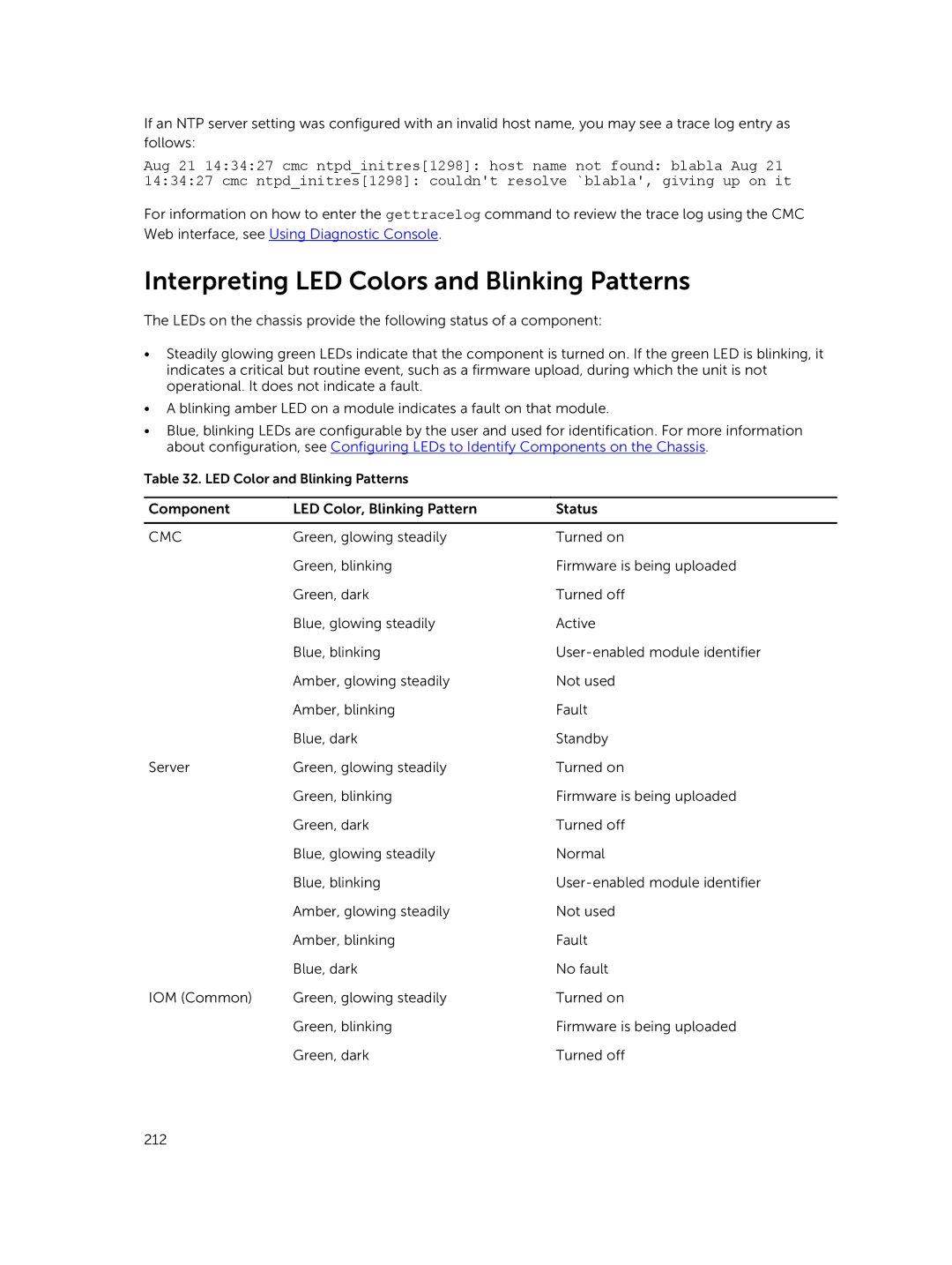
Troubleshooting Network Time Protocol NTP Errors
Racadm config -g cfgRemoteHosts -o cfgRhostsNtpMaxDist
Racadm config -g cfgRemoteHosts -o cfgRhostsNtpEnable
Jan 8 200240 cmc ntpd1423 synchronized to LOCAL0, stratum
Interpreting LED Colors and Blinking Patterns
DC OK
Troubleshooting Non-responsive CMC
AC OK
Recovering Firmware Image
Observing LEDs to Isolate the Problem
Obtain Recovery Information from DB-9 Serial Port
Troubleshooting Network Problems
Troubleshooting Controller
Page
Using LCD Panel Interface
LCD Navigation
Main Menu
KVM Mapping Menu
Settings
DVD Mapping
Enclosure Menu
IP Summary Menu
Diagnostics
Default Screen
Front Panel LCD Messages
LCD Language
LCD Module and Server Status Information
RPM
IOM a
Current blower speed in RPM
Related. For more information, see LCD Error Messages
Web interface
Frequently Asked Questions
Racadm subcommand Transport Error RC=-1
Racadm command failed
Racadm chassislog help clear
Managing and Recovering a Remote System
Racadm getconfig -g cfgOobSnmp
Active Directory
No feature card inserted Error cant open file
FlexAddress and FlexAddressPlus
No feature card inserted
IOM