Supported Rack Configuration
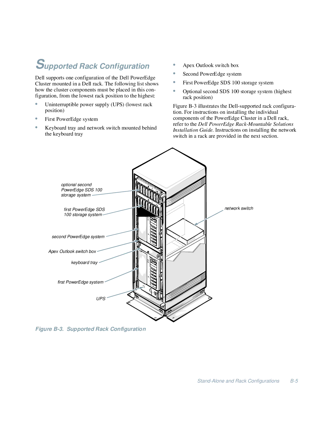
Dell supports one configuration of the Dell PowerEdge Cluster mounted in a Dell rack. The following list shows how the cluster components must be placed in this con- figuration, from the lowest rack position to the highest:
•Uninterruptible power supply (UPS) (lowest rack position)
•First PowerEdge system
•Keyboard tray and network switch mounted behind the keyboard tray
•Apex Outlook switch box
•Second PowerEdge system
•First PowerEdge SDS 100 storage system
•Optional second SDS 100 storage system (highest rack position)
Figure B-3 illustrates the Dell-supported rack configura- tion. For instructions on installing the individual components of the PowerEdge Cluster in a Dell rack, refer to the Dell PowerEdge Rack-Mountable Solutions Installation Guide. Instructions on installing the network switch in a rack are provided in the next section.
optional second PowerEdge SDS 100 storage system
first PowerEdge SDS 100 storage system
second PowerEdge system |
Apex Outlook switch box ![]()
keyboard tray ![]()
first PowerEdge system ![]()
UPS ![]()
Figure B-3. Supported Rack Configuration
network switch