Dell Computer Corporation | Date:________________________ |
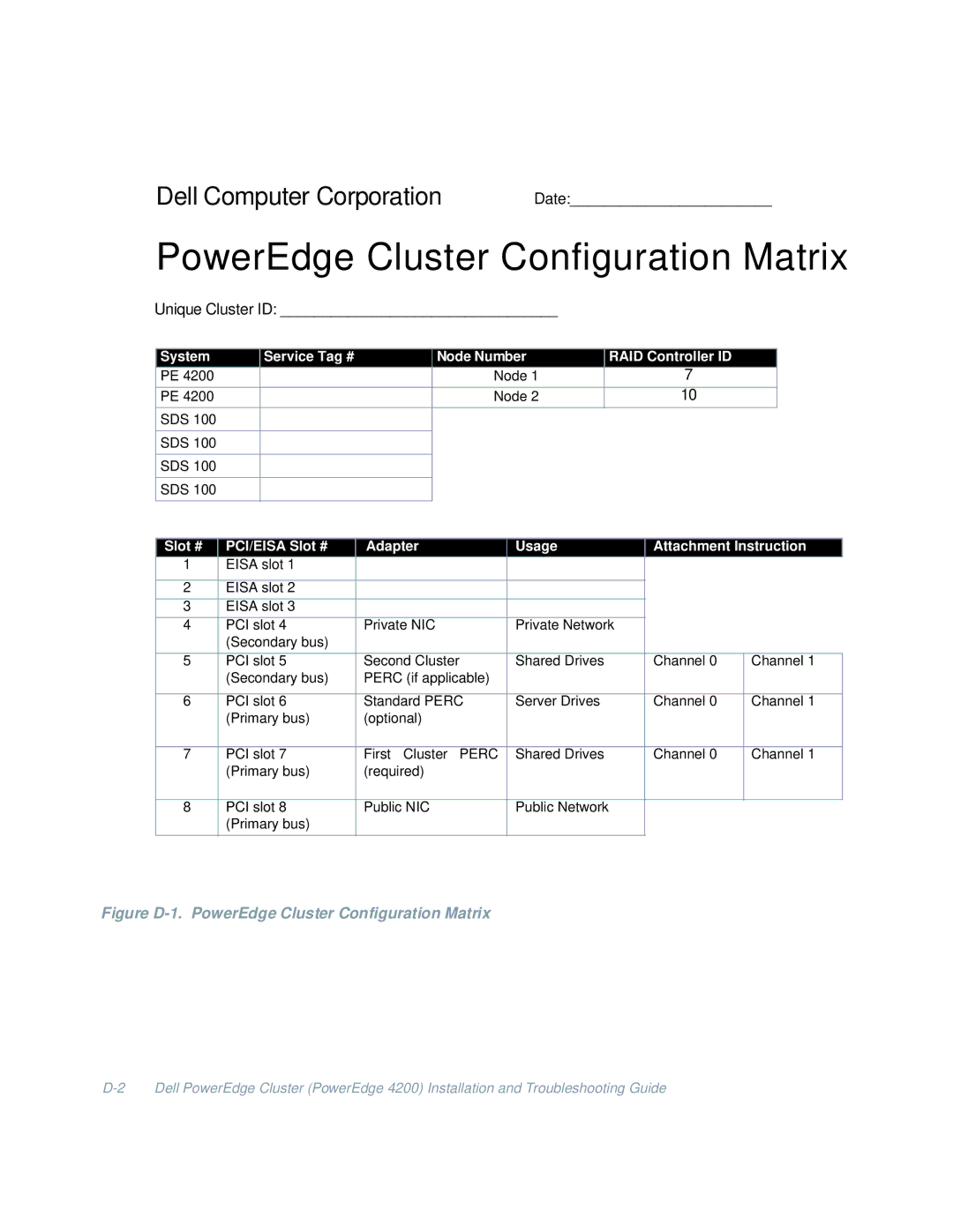
PowerEdge Cluster Configuration Matrix
Unique Cluster ID: _________________________________
System |
| Service Tag # |
| Node Number |
| RAID Controller IDD |
|
| |||
|
|
|
|
| |||||||
PE 4200 |
|
|
| Node 1 |
| 7 |
|
| |||
|
|
|
|
|
|
|
|
|
|
| |
PE 4200 |
|
|
| Node 2 |
| 10 |
|
| |||
SDS 100 |
|
|
|
|
|
|
|
|
|
|
|
|
|
|
|
|
|
|
|
|
|
|
|
SDS 100 |
|
|
|
|
|
|
|
|
|
|
|
|
|
|
|
|
|
|
|
|
|
|
|
SDS 100 |
|
|
|
|
|
|
|
|
|
|
|
|
|
|
|
|
|
|
|
|
|
|
|
SDS 100 |
|
|
|
|
|
|
|
|
|
|
|
|
|
|
|
|
|
|
|
|
|
|
|
|
|
|
|
|
|
|
|
|
|
|
|
Slot # | PCI/EISA Slot # | Adapter | Usage |
|
| Attachment Instruction | |||||
1 | EISA slot 1 |
|
|
|
|
|
|
|
|
| |
|
|
|
|
|
|
|
|
|
|
| |
2 | EISA slot 2 |
|
|
|
|
|
|
|
|
| |
|
|
|
|
|
|
|
|
|
|
| |
3 | EISA slot 3 |
|
|
|
|
|
|
|
|
| |
|
|
|
|
|
|
| |||||
4 | PCI slot 4 | Private NIC | Private Network |
|
|
|
| ||||
| (Secondary bus) |
|
|
|
|
|
|
|
|
| |
|
|
|
|
|
|
|
| ||||
5 | PCI slot 5 | Second Cluster | Shared Drives |
|
| Channel 0 | Channel 1 | ||||
| (Secondary bus) | PERC (if applicable) |
|
|
|
|
|
|
| ||
|
|
|
|
|
|
|
| ||||
6 | PCI slot 6 | Standard PERC | Server Drives |
|
| Channel 0 | Channel 1 | ||||
| (Primary bus) | (optional) |
|
|
|
|
|
|
| ||
|
|
|
|
|
|
|
| ||||
7 | PCI slot 7 | First Cluster PERC | Shared Drives |
|
| Channel 0 | Channel 1 | ||||
| (Primary bus) | (required) |
|
|
|
|
|
|
| ||
|
|
|
|
|
|
|
|
| |||
8 | PCI slot 8 | Public NIC | Public Network |
|
|
|
|
| |||
| (Primary bus) |
|
|
|
|
|
|
|
|
| |
|
|
|
|
|
|
|
|
|
|
|
|