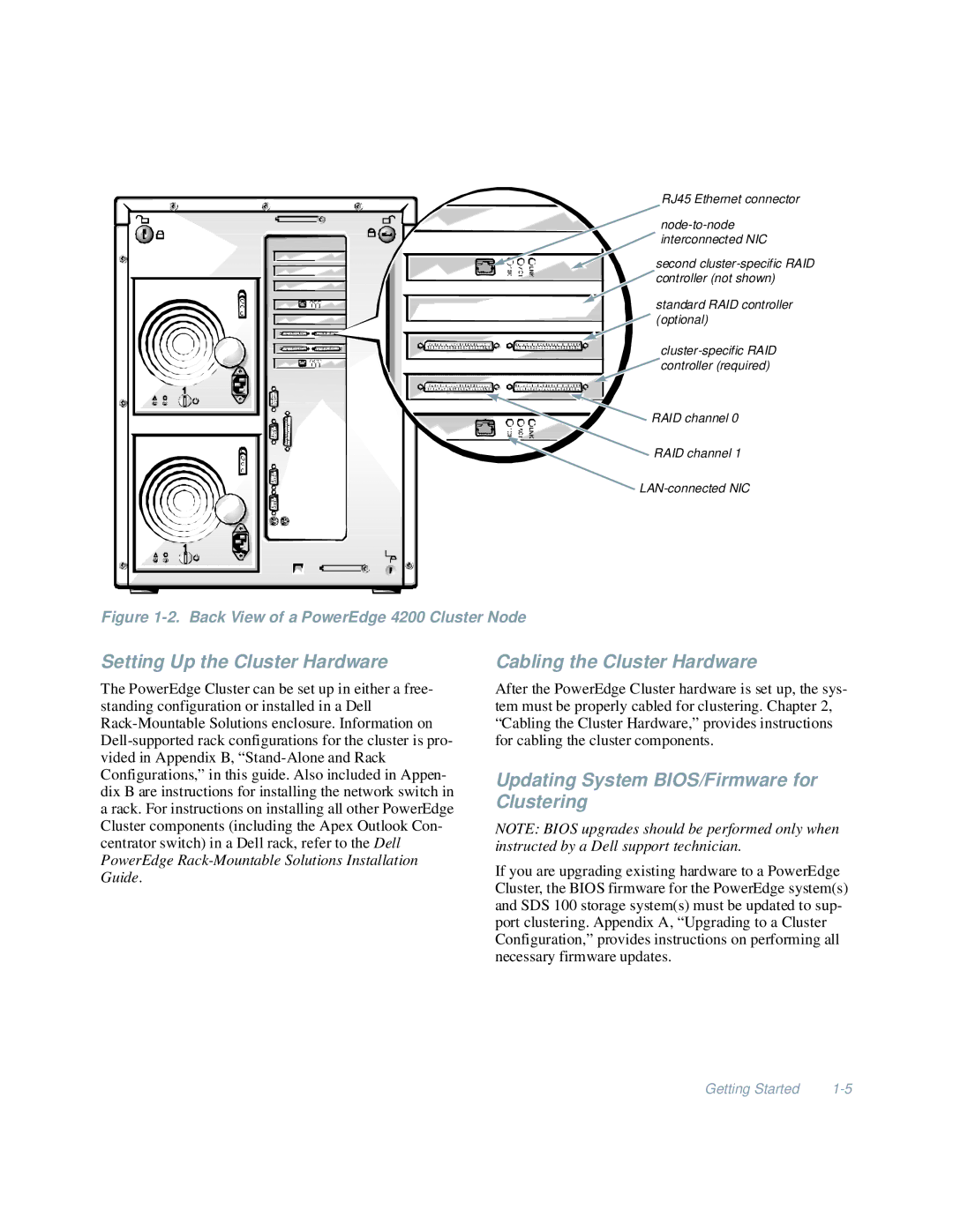
RJ45 Ethernet connector
interconnected NIC |
second |
controller (not shown) |
standard RAID controller |
(optional) |
controller (required) |
RAID channel 0 |
![]() RAID channel 1
RAID channel 1
![]()
Figure 1-2. Back View of a PowerEdge 4200 Cluster Node
Setting Up the Cluster Hardware
The PowerEdge Cluster can be set up in either a free- standing configuration or installed in a Dell
Cabling the Cluster Hardware
After the PowerEdge Cluster hardware is set up, the sys- tem must be properly cabled for clustering. Chapter 2, “Cabling the Cluster Hardware,” provides instructions for cabling the cluster components.
Updating System BIOS/Firmware for Clustering
NOTE: BIOS upgrades should be performed only when instructed by a Dell support technician.
If you are upgrading existing hardware to a PowerEdge Cluster, the BIOS firmware for the PowerEdge system(s) and SDS 100 storage system(s) must be updated to sup- port clustering. Appendix A, “Upgrading to a Cluster Configuration,” provides instructions on performing all necessary firmware updates.
Getting Started |