Dell 4200 manual Mounting, Cabling, and Configuring the Cluster Hardware

Models: 4200

1 82
Download 82 pages 44.18 Kb
Page 54
Image 54

You may choose to install a standard PowerEdge Expandable RAID Controller as the second RAID controller in your system instead of a cluster-enabled RAID controller. This is the configuration you will use if you plan to set up the internal hard-disk drives in the cluster node in a RAID array. In this configuration, install the standard RAID controller in PCI slot 6. Because this standard RAID controller will handle the system partition on the cluster node, do not disable this controller’s BIOS.

PCI slots 4 and 8 should be used for the cluster NIC cards. Use PCI slot 8 for the public local area network (LAN) and PCI slot 4 for the private node-to-node network.

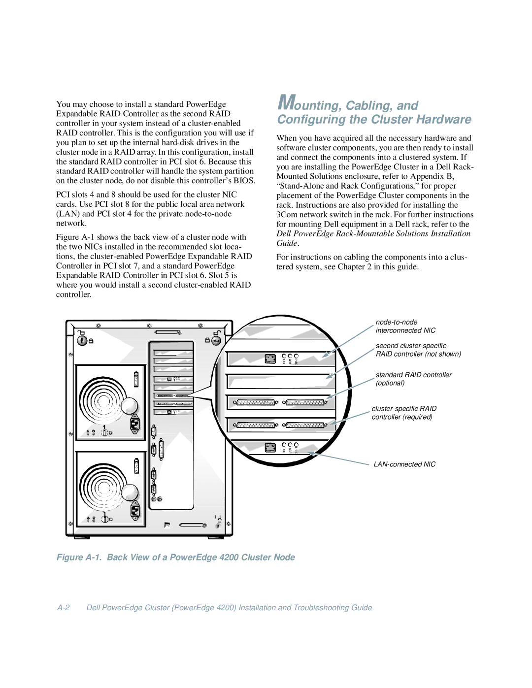
Figure A-1 shows the back view of a cluster node with the two NICs installed in the recommended slot loca- tions, the cluster-enabled PowerEdge Expandable RAID Controller in PCI slot 7, and a standard PowerEdge Expandable RAID Controller in PCI slot 6. Slot 5 is where you would install a second cluster-enabled RAID controller.

Mounting, Cabling, and Configuring the Cluster Hardware

When you have acquired all the necessary hardware and software cluster components, you are then ready to install and connect the components into a clustered system. If you are installing the PowerEdge Cluster in a Dell Rack- Mounted Solutions enclosure, refer to Appendix B, “Stand-Alone and Rack Configurations,” for proper placement of the PowerEdge Cluster components in the rack. Instructions are also provided for installing the 3Com network switch in the rack. For further instructions for mounting Dell equipment in a Dell rack, refer to the Dell PowerEdge Rack-Mountable Solutions Installation Guide.

For instructions on cabling the components into a clus- tered system, see Chapter 2 in this guide.

node-to-node interconnected NIC

second cluster-specific

RAID controller (not shown)

standard RAID controller

(optional)

cluster-specific RAID

controller (required)

LAN-connected NIC

Figure A-1. Back View of a PowerEdge 4200 Cluster Node

A-2 Dell PowerEdge Cluster (PowerEdge 4200) Installation and Troubleshooting Guide

Page 54
Image 54
Dell 4200 manual Mounting, Cabling, and Configuring the Cluster Hardware