MITX-430/MITX-440-DVI-2E
Contact Address
Contents
Contents
Operation
OEM-Reserved Status Code Ranges
List of Tables
List of Tables
Table A-1
List of Tables
List of Figures
List of Figures
Overview of Contents
About this Manual
Abbreviations
About this Manual
GBE
PWM
Conventions
Notation Description
Bold
Comments and Suggestions
Summary of Changes
About this Manual About this Manual
Part Number Publication Date Description
About this Manual
About this Manual
Single Core Processor Board Features
Features
Function Features
Introduction
USB
Introduction
MITX-440-DVI-2E
Dual Core Processor Board Features
Introduction
Standard Compliances
Standard Compliances
Standard Description
Declaration of Conformity
Mechanical Data
Board Accessories
Ordering Information
Supported Board Models
Product Identification
Dual Core Processor Board -Serial Number Location
Introduction
Environmental and Power Requirements
Hardware Preparation and Installation
Environmental Requirements
Environmental Requirements
Critical Temperature Spots
Hardware Preparation and Installation
Maximum Allowable Temperature 0C
Thermal Requirements
Full Loading Running Burn-in Test
Power Requirements Single Core Processor Board
Idle Mode Power Consumption
Power Requirements Dual Core Processor Board
VGA and Lvds dual display, without DVI display
Board Thermal Management
Board Thermal Management and Placement
Board Thermal Management
Shipment Inspection
Unpacking and Inspecting the Board
Environmental Damage
Preparing the Installation Environment
Installing the Processor Cooler
Processor Cooler Installation and Removal
Memory Module Installation and Removal
Removing Memory Module
Hardware Preparation and Installation
Board Layout
Controls, LEDs, and Connectors
Dual Core Motherboard Components
Controls, LEDs, and Connectors
Clear Cmos P3
Connectors
Lvds Header J5
Clear Cmos
Lvds Power
Lvds Backlight Header P23
Mini IDE Header J8
USB Flash Header Pin Definition
USB Flash Header P10
ELO Touch Screen Header P6
USB Header P12
USB Header Pin Definition
ELO Touch Screen Header Pin Definition
Gpio Header P4
COM Header P9, P27
11 RS-232/422/485 P18
12 RS-232/422/485 Jumper Selection P28
Power COM P8, P26
13 COM4, COM5 Header Pin Definition
14 COM4, COM5 Pin9 Selection
15 TPM Header Pin Definition
TPM Header P2
Front Panel Header P15
LPT Header P11
16 LPT Header Pin Definition
17 Front Panel Header Pin Definition
18 Bios Program Header Pin Definition
Bios Program Header P16
Fan Header P1, P13
19 Smart Fan Header Pin Definition
Mini Pcie LED P14
20 Mini Pcie Wireless LAN LED Header Pin Definition
Case Open Header P25
21 Case Open Header Pin Definition
Functional Description
Block Diagram
Pineview-D Processor
SMBus Interface and Devices
Functional Description
Board I2C Device Connection
Ethernet Interfaces
System Memory
PCI-E Port
I2C Device Address
PCI-E Connection
USB Interface
USB Ports Connection
VGA, LVDS, LPC, and Audio Interface
Gpio Configuration
Bios Device
DVI Interface
11 IDE
ICH8-M Gpio Definition
12.2 ICH8-M Gpio
GPIO12
Well Default Signal Description Implementation
Power Name Type
GPIO36
Chipset
Clock Generator
Video
Storage
Super I/O
HW Monitor
SPI Flash
Power Management
Watchdog Timer
Debug
Manageability
Functional Description
Initiating Setup
Boot Process
Operation
Post
Setup Utility
Setup Utility
Main Menu
Operation
Advanced Menu
Legacy Oprom Support
Advanced Menu
Trusted Computing
Acpi Settings
CPU Configuration
S5 RTC Wake Setting
Execute Disable Bit
IDE Configuration
CRT LFP DVI CRT +LFP CRT +DVI
10 IGD-LCD Control
Ehci Hand-off
11 USB Configuration
12 EMC2103 H/W Monitor
13 Super IO Configuration
15 Serial Port 2 Configuration
14 Serial Port 1 Configuration
17 Serial Port 4 Configuration
16 Serial Port 3 Configuration
19 Serial Port 6 Configuration
18 Serial Port 5 Configuration
21 Watchdog Timer Configuration
20 Parallel Port Configuration
23 Serial Port Console Redirection
22 W83627UHG H/W Monitor
24 COM1 and COM2 Console Redirection Settings
Bits per second
25 Chipset Menu
Chipset Menu
26 Host Bridge
27 South Bridge
28 Boot Menu
Boot Menu
Save & Exit Menu
Security Menu
29 Security Menu
30 Save & Exit Menu
Status Code Ranges
Post Codes
31 Status Code Ranges
Status Code Range Description
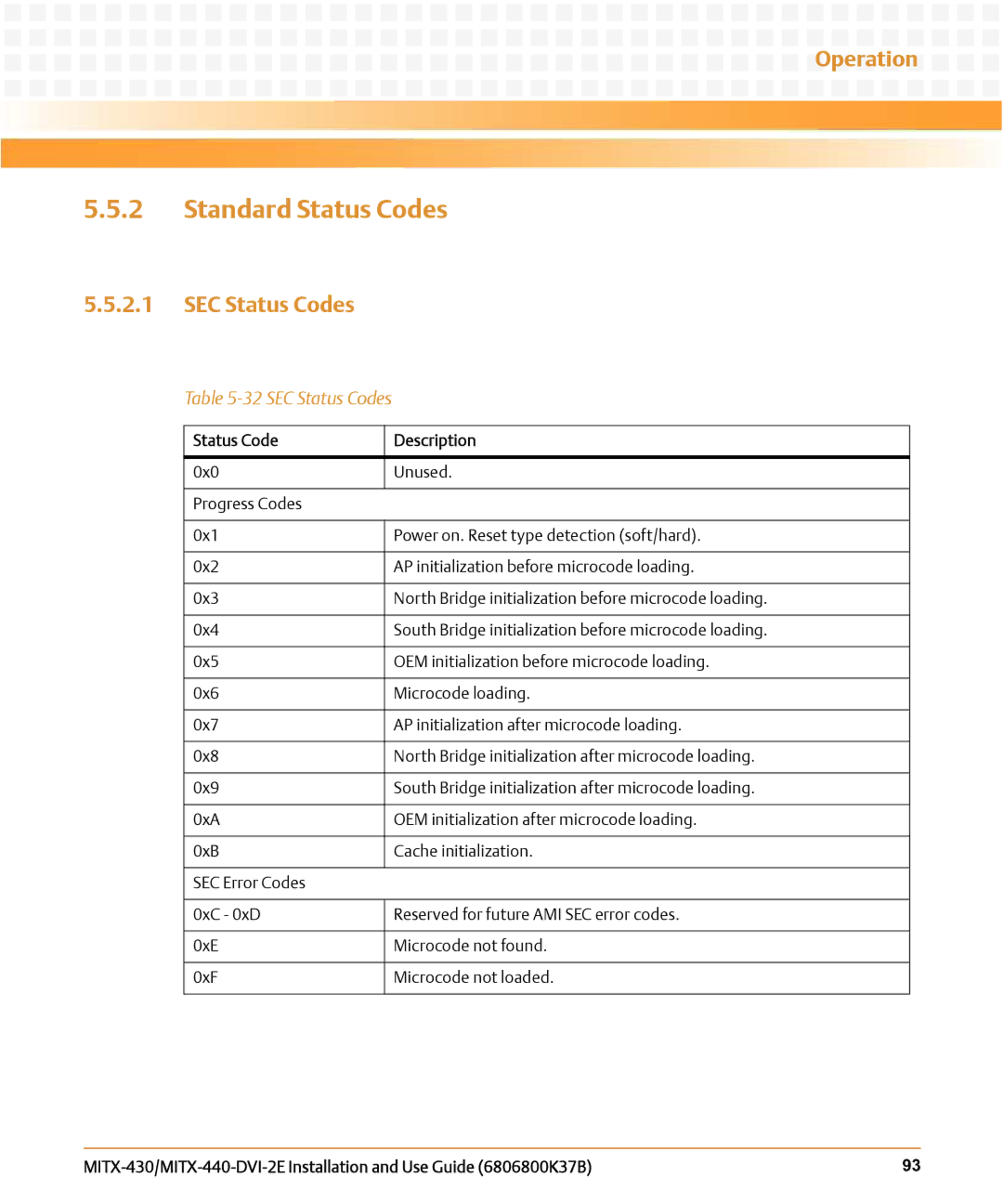
SEC Status Codes
Standard Status Codes
32 SEC Status Codes
Status Code Description
33 PEI Status Codes
Operation PEI Status Codes
0x36
S3 Resume Progress Codes
PEI Beep Codes
34 PEI Beep Codes
# of Beeps Description
35 DXE Status Codes
Operation DXE Status Codes
Operation
Operation
CPU Exception Status Codes
DXE Beep Codes
36 DXE Beep Codes
37 CPU Exception Status Codes
38 ASL Status Codes
ASL Status Codes
39 OEM-Reserved Status Code Ranges
OEM-Reserved Status Code Ranges
Operation
Supported Operating System
Operating System and Driver Support
Supported Drivers
Supported Drivers
Operating System and Driver Support
Table A-2 Related Specifications
Related Specifications
ARelated Documentation
Emerson Embedded Communications Computing Documents
108
Related Documentation
Safety Notes
EMC
Safety Notes
Vcci
Installation
Safety Notes
Safety Notes
System Overheating Cooling Vents
Operation
Safety Notes
Safety Notes
Personal Injury or Short Circuits Blade or Power Supply
Configuration Switches/Jumpers
Grounding
Connectors and Cabling
Safety Notes
PEM
Safety Notes
Fans/Blowers
Safety Notes
Expansion and FRU Replacement
Safety Notes
System Damage If the system is overloaded it gets damaged
Hot Swap
SFP/SFP+ Modules
PMC Modules
Laser
Battery
Safety Notes
Environment
Safety Notes
Sicherheitshinweise
Sicherheitshinweise
System Installation
Sicherheitshinweise
Sicherheitshinweise
Überhitzung des Systems Lüftungsöffnungen
Betrieb
Sicherheitshinweise
Sicherheitshinweise
Verletzungen oder Kurzschlüsse Blade oder Stromversorgung
Schaltereinstellungen
Erdung
Stecker und Verkabelung
Sicherheitshinweise
PEM
Sicherheitshinweise
Lüfter
Beschädigung der Lüfter
Erweiterung und FRU Austausch
Sicherheitshinweise
Hot Swap
Fehlfunktion des Produktes und/oder Verletzungsgefahr
PMC Module
Batterie
Sicherheitshinweise
Umweltschutz
Index
Index
Page
Embedded Computing
HOW to Reach Literature and Technical Support

