MVME2500
Contact Address
Contents
Contents
Contents
Memory Maps and Registers
Emerson Network Power Embedded Computing Documents
Safety Notes Sicherheitshinweise Index
List of Tables
List of Tables
List of Figures
Figure A-1
List of Figures
Overview of Contents
About this Manual
Abbreviations
About this Manual
Conventions
USB
Vita
VME
About this Manual About this Manual
Summary of Changes
Documentation, on
Key Features of the MVME2500
Introduction
Overview
Introduction
KB Mram
8 KB VPD Eeprom
Standard Compliances
Board Standard Compliances
Mechanical Data
Ordering Information
Mechanical Data
Available Board Variants
Available Board Accessories
VME-HDMNTKIT
VME-64GBSSDKIT
SERIAL-MINI-D
Product Identification
Serial Number Location
Hardware Preparation and Installation
Hardware Preparation and Installation
Unpacking and Inspecting the Board
Requirements
Environmental Requirements
Environmental Requirements
Grms
Power Requirements
Power Requirements
Configuring the Board
Equipment Requirements
Installing Accessories
Rear Transition Module
Installation Procedure
2 PMC/XMC Support
Installing and Removing the Board
Hardware Preparation and Installation
Completing the Installation
Controls, LEDs, and Connectors
Board Layout
Controls, LEDs, and Connectors
Front Panel
Reset Switch
LEDs
Front Panel LEDs
User
Fail
GENET1 TSEC1
Speed
Connectors
Onboard LEDs
Onboard LEDs Status
Front Panel Connectors
Front Panel Tri-Speed Ethernet Connector J1
1.1 RJ45 with Integrated Magnetics J1
Front Panel Serial Port J4
Front Panel Serial Port J4
Controls, LEDs, and Connectors USB Connector J5
VMEBus P1 Connector
USB Connector J5
VMEbus P1 Connector
DS0 BR1 Lword GA2 Write BR2
GND BR3
GA3 Dtack
GA4
Controls, LEDs, and Connectors VMEBus P2 Connector
VMEbus P2 Connector
Onboard Connectors
Flash Program Connector P7
Flash Programming Header P7
Sata Connector J3
Custom Sata Connector J3
GND Sata Power Enable Sata TX + Sata Detect
Sata RX
PMC Connectors
10 PMC J11 Connector
11 PMC J12 Connector
12 PMC J13 Connector
GND CBE7 CBE6 CBE5 CBE4
PAR64
13 PMC J14 Connector
Jtag Connector P6
14 Jtag Connector P6
GPO0 Scan 2 TMS Scan 2 TDO Scan 2 TCK
GND Scan 2 TDI Scan 3 TMS Scan 3 TCK1 Scan 3 TDO
Scan 3 TCK
GND Scan 4 TDI Scan 4 TCK Scan 4 Trst Scan 5 TMS Scan 5 TDO
Controls, LEDs, and Connectors COP Connector P6
SD Connector J2
16 SD Connector J2
15 COP Header P10
XMC Connector XJ2
17 XMC Connector XJ2 Pinout
Miscellaneous P2020 Debug Connectors
18 P20x0 Debug Header
Switches
Geographical Address Switch S1
Trigin MSRCID4 GND
VME Scon SEL2
GAP4
GAP3
GAP2
SMT Configuration Switch S2
Masterwpdisa
Bled
Gbemuxsel
Plane
Block Diagram
Functional Description
Chipset
1 e500 Processor Core
Integrated Memory Controller
Functional Description
PCI Express Interface
Local Bus Controller LBC
Secure Digital Hub Controller Sdhc
6 I2C Interface
Duart
DMA Controller
Enhanced Three-Speed Ethernet Controller eTSEC
General Purpose I/O Gpio
Timers
14 P20x0 Hardware Configuration Pins
System Memory
Common On-Chip Processor COP
Internal Timer
Watchdog Timer
Fpga Tick Timer
Ethernet Interfaces
SPI Bus Interface
SPI Flash Memory
SPI Flash Programming
Firmware Redundancy
SPI Device Multiplexing Logic
Crisis Recovery
Front Uart Control
Rear Uart Control
PMC/XMC Sites
Sata Interface
PMC Add-on Card
XMC Add-on Card
VME Support
12 USB
13 I2C Devices
11.1 Tsi148 VME Controller
Reset/Control Fpga
Power Management
Onboard Voltage Supply Requirement
Voltage Supply Requirement
Power Up Sequencing Requirements
Reset Structure
Clock Structure
Real-Time Clock Battery
Reset Sequence
Thermal Management
Thermal Interrupt Threshold
Post Code Indicator
Post Code Indicator on the LED
Debugging Support
Jtag Chain and Board
Transition Module Features
Rear Transition Module RTM
Custom Debugging
SBC
Functional Description
Memory Maps and Registers
Memory Map
Physical Address Map
Flash Memory Map
Linux Devices Memory Map
Memory Maps and Registers
Flash Memory Map
Linux Devices Memory Map
Programmable Logic Device PLD Registers
PLD Revision Register
PLD Year Register
PLD Revision Register
PLD Month Register
PLD Day Register
PLD Sequence Register
PLD Power Good Monitor Register
PLD Power Good Monitor Register
Wrgd RGD Pwrg Oper Reset
Rsvd Pwrv
PLD LED Control Register
10 PLD LED Control Register
PWRV1P2SWPWRG
PLD PCI/PMC/XMC Monitor Register
11 PLD PCI/PMC/XMC Monitor Register
PMC1PN
PLD U-Boot and TSI Monitor Register
PLD Boot Bank Register
12 PLD U-Boot and TSI Monitor Register
13 PLD Boot Bank Register
Bootb Boots
Locka
Wpdi WPN Ugen Flash Sabled Oper Reset
PLD Write Protect and I2C Debug Register
14 PLD Write Protect and I2C Debug Register
Rsvd Master Flash I2CDEB Serial
I2CDEBUGEN=0
PLD Test Register
15 PLD Test Register
16 PLD Test Register
Rsvd NMI TICK0INT TICK1INT TICK2INT Oper Reset
PLD GPIO2 Interrupt Register
17 PLD GPIO2 Interrupt Register
PLD Shutdown and Reset Control and Reset Reason Register
18 PLD Shutdown and Reset Control and Reset Reason Register
Cpureset Wdtime Lrsto
Dnmask OUT Oper Reset
PLD Watchdog Timer Refresh Register
19 PLD Watchdog Timer Refresh Register
PLD Watchdog Timer Count Register
21 PLD Watchdog Timer Count Register
PLD Watchdog Control Register
20 PLD Watchdog Control Register
External Timer Registers
Prescaler Register
22 Prescaler Register
COC ENC Oper Reset
Control Registers
23 Control Registers
Ints Cint
Compare High and Low Word Registers
24 Compare High Word Registers
25 Compare Low Word Registers
Counter High and Low Word Registers
26 Counter High Word Registers
27 Counter Low Word Registers
102
Boot System
Accessing U-Boot
Boot Options
Booting from a Network
Boot System
Booting from an Optional Sata Drive
Booting from a USB Drive
Booting from an SD Card
Booting VxWorks Through the Network
Using the Persistent Memory Feature
Analyzing Kernel Log Files after a Kernel Panic
MVME2500 Specific U-Boot Commands
MVME2500 Specific U-Boot Commands
Boot System
Updating U-Boot
Sf probe
112
Reset Configuration
POR Configuration Settings
Programming Model
Programming Model
Config Config Pins Selection Remarks ETSEC2 Sgmii LGPL1
ETSEC3 Sgmmi TSEC1588ALARM
Ecmdc
ETSEC1 TSEC1TXD0
Config Config Pins Selection Remarks Boot ROM
TSEC1TXER
LWE1/LBS1
TSEC2TXER
Interrupt Controller
MVME2500 Interrupt List
I2C Bus Device Addressing
Ethernet PHY Address
I2C Bus Device Addressing
PHY Types and MII Management Bus Address
Other Software Considerations
Mram
Quad Uart
TSEC3
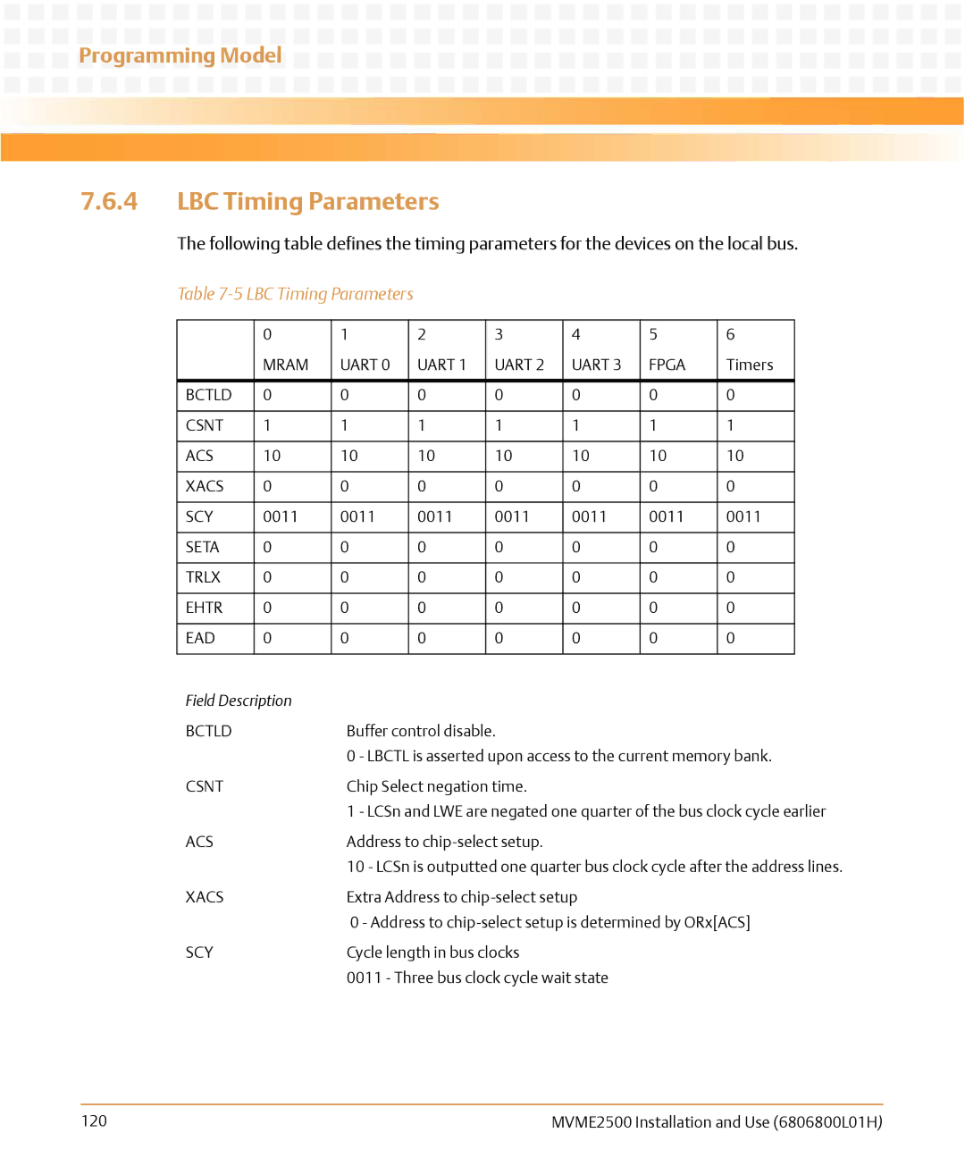
LBC Timing Parameters
LBC Timing Parameters
Clock Distribution
Clock Distribution
System Clock
System Clock
Real Time Clock Input
Local Bus Controller Clock Divisor
124
Replacing the Battery
Replacing the Battery
Replacing the Battery
Replacement Procedure
128
Emerson Network Power Embedded Computing Documents
Related Documentation
Related Specifications
Table B-3 Related Specifications
Manufacturers’ Documents
Related Documentation
PCI-SIG
SATA-IO
132
Safety Notes
EMC Results pending testing
Installation
Safety Notes
Operation
Cabling and Connectors
Battery
Sicherheitshinweise
Betrieb
Sicherheitshinweise
139
Kabel und Stecker
Batterie
Umweltschutz
142
Index
Index
Page
HOW to Reach Literature and Technical Support


 Programming Model