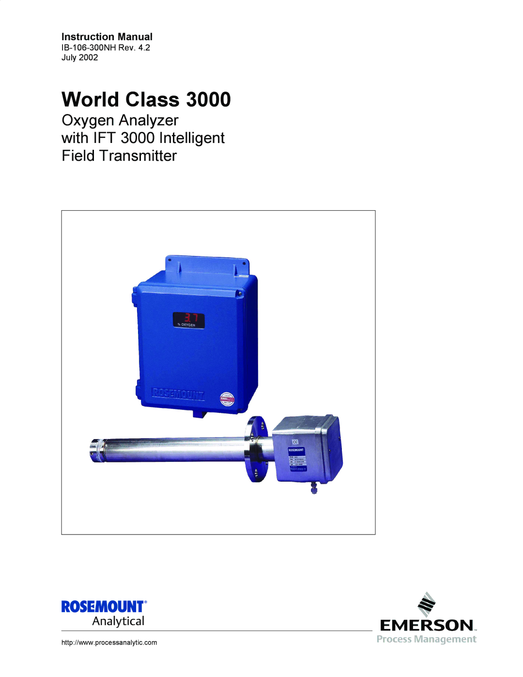
World Class
Essential Instructions
Effective May, 1999 Rev
Highlights of Changes
Summary
Effective November, 2001 Rev
Appendix a
Diffusion assembly illustrations, Figure A-13 and A-14
Effective February, 1992 Rev
Appendix B
Effective January, 1995 Rev
Effective June, 1994 Rev
Appendix D
Effective June, 1999 Rev
Appendix E
Effective April, 1995 Rev
Appendix J
Effective June, 1995 Rev
Page
World Class
Table of Contents
12. IFT Interconnect Board Output Connections
List of Illustrations
Calibrate O2 Sub-Menu
List of Tables
World Class
Definitions
Preface
World Class
Glossary of Terms
Semiautomatic Calibration
Reference Air
Thermocouple
Vee Deflector
Complete World Class 3000 System
What YOU Need to Know
Use this Quick Start Guide if
Quick Start Guide
Quick Start Guide for IFT 3000 Systems
Line Voltage Jumper Section Install
Performing a Manual Semiautomatic Calibration
Setting up the Analog Output
Technical Support Hotline
Hart Communicator Fast KEY Sequences
Component Checklist of Typical System Package Contents
Section Description and Specifications
Scope
System Overview
System Description
System Features
System Configuration
World Class
Options
Standard
HPS
World Class
World Class
Oxygen Analyzer Probe Installation
Section Installation
Probe Installation Sheet 1
Probe Installation Sheet 2
Probe Installation Sheet 3
Probe Installation Sheet 4
Probe Installation Sheet 5
Orienting the Optional Vee Deflector
Reference Air Package
Service Required
Refer to -7for fuse locations and specifications
Intelligent Field Transmitter IFT Installation
Power Supply Board Jumper Configuration
Signal Wire Routing
IFT Power Supply Board Jumpers
Wiring Layout for IFT Systems without HPS
Output Jumper
Heater Power Supply Installation
Analog Output
Condition during Microcontroller failure Jumper
10. IFT Microprocessor Board
11. Interconnect Board Jumper Configuration
Refer to -17for fuse locations and specifications
13. Outline of Heater Power Supply Electrical Connections
J8 + +
CURRENT/VOLTAGE Selector Switch
15. Heater Power Supply Wiring Connections
17. Jumpers on HPS Mother Board
Gas Connections
Multiprobe Calibration GAS Sequencer Installation
19. MPS Gas Connections
Refer to -20for fuse locations and specifications
20. MPS Probe Wiring
World Class
World Class
Configuring the Analog Output
Section Setup
Setting Calibration Parameters
Overview
Configuring Efficiency Calculations
Setting the O2 Alarm Setpoints
Configuring the Relay Outputs
Analog Output Calibration
Calibration
System Calibration
Overview
Liquid Carbonic GAS Corp Specialty GAS Laboratories
Calibration Methods
Scott Environmental TECHNOLOGY, INC. Scott Specialty Gases
World Class
Portable Rosemount Oxygen Calibration Gas Kit
Fully Automatic Calibration
Typical Automatic Calibration System
Figure analog output
Automatic Calibration Parameters
Calibration Record For Rosemount Analytical In Situ O2 Probe
World Class
Hart Communicator Interface Devices
Section General User Interface GUI Operation
Internal View External View
Deluxe Version IFT Displays and Controls
MENU, SUB-MENU, Help Or Parameter Name Message Probe Data
Quick Reference Chart
Calibrate O2
Help KEY
Probe Data Sub-Menu
Calibrate O2 SUB-MENU Setup SUB-MENU
SUB-MENU Selection Parameter Description
Quick Reference Chart Sheet 1
Quick Reference Chart Sheet 2
Quick Reference Chart Sheet 3
Quick Reference Chart Sheet 4
Quick Reference Chart Sheet 5
Calibrate O2 Sub-Menu
See Table
SUB-MENU Setup Setting Selection
Display Description
SUB-MENU Selection Parameters Description
Setup Sub-Menu
Range Values
Xfer Fnct
Normal Range Values
Dual Range Setup
Efficiency Constants
Constant United States Europe GAS OIL
Special Troubleshooting Notes
Section Troubleshooting
System Troubleshooting
IFT Status Codes
Heater Problem
Heater Troubleshooting Problem
Cell Troubleshooting Problem
Cell Problem
Status is LowO2 Cell mV = -127 mV
Status is ResHi or CalEr Cell mV = -20 to 120 mV normal
Status is Res Hi Cell mV = -120 to 20 mV
IFT Troubleshooting Problem
IFT Problem
Faulty GUI or LDP IFT LED is Flashing
MPS Troubleshooting Problem
MPS Problem
Status is NoGas Cell mV is between -20 to 120 mV
Status is ResHi or CalEr Cell mV is between -20 to 120 mV
Performance Problem Troubleshooting
Performance Problem Process Response is Suspect
World Class
Section Return of Material
World Class
Section Appendices
Appendix a
Figure A-2. Main Probe Components
Oxygen Analyzer Probe General
Table A-1. Specifications for Oxygen Analyzing Equipment.1
Cell and Flange Assembly
Probe Assembly Exterior
Probe Tube Assembly
Snubber Diffusion Assembly
Cell General
Inner Probe Assembly
Abrasive Shield Assembly
Cable Assembly
Probe Junction BOX
Probe Options
View a
Ceramic Diffusion Assembly
Figure A-8. Ceramic Diffusion/Dust Seal Assembly
Probe Mounting Jacket Options
Snubber Diffusion/Dust Seal Assembly
Figure A-15. Bypass Probe Option Sheet 1
Figure A-15. Bypass Probe Option Sheet 2
Group Code Description
Extended Temperature By-Pass Arrangements 2400F 1300C
Probe Troubleshooting
Probe Troubleshooting
Probe Faults
Table A-2. Fault Finding Symptom Check Remedy
World Class
Figure A-16. Flowchart of Probe Related Problems, #1
Figure A-17. Flowchart of Probe Related Problems, #2
Cell Replacement
Service and Normal Maintenance
Probe Recalibration
Figure A-18. Cell Wiring Connection
Optional Ceramic Diffusion
Element Replacement
General
World Class
Figure A-21. Probe Junction Box Mechanical Connections
Replacement of Contact Thermocouple Assembly
Contact Heater Screws Not Shown Thermocoupler
World Class
Figure A-24. Oxygen Analyzer Probe, Cross-Sectional View
Figure A-25. High Temperature Corrosive Environment Kit
Figure A-7 3D39003G01 Abrasive Shield Assembly, 3 ft 0.9 m
Replacement Parts
Figure A-9 3535B63G01 Flame Arrestor Diffuser Dust Seal
World Class
Front
Theory of Operation
HPS 3000 Troubleshooting
Figure B-4. HPS Troubleshooting Flowchart, #1
Symptom
Figure B-5. HPS Troubleshooting Flowchart, #2
Figure B-6. HPS Troubleshooting Flowchart, #3
Service and Normal Maintenance
Daughter Board Replacement
Figure B-7. Heater Power Supply, Exploded View
Replacement Parts
World Class
Figure D-1. MPS 3000 Multiprobe Calibration Gas Sequencer
Nema 4X IP56
Figure D-3. Typical Automatic Calibration System
Supplied Line Customer
Bebco Model Z-PURGE Rear View
MPS 3000 Troubleshooting
Figure D-5. MPS Troubleshooting Flowchart
Solenoid Valve Replacement
4543
Pressure Regulator Maintenance
Flowmeter Adjustments
Index No
World Class
Microprocessor Board
Power Supply Board
Interconnect Board
GUI/LED Display Board Optional
Heater optional
Table E-1. Specifications for Intelligent Field Transmitter
Purge optional
Theory of Operation
Probe
Heater Power Supply Optional IFT
IFT Troubleshooting
IFT 3000 Troubleshooting
Microprocessor Status LED
Equipment Status LCD Displays
Figure E-3. IFT Troubleshooting Flowchart, #1
Figure E-4. IFT Troubleshooting Flowchart, #2
Symptom Microprocessor Board LED is Steady on
Symptom Component Failure
Table E-2. GUI Equipped IFT Fault Finding
Transformer Replacement
Fuse Replacement
Figure E-6. Intelligent Field Transmitter, Exploded View
Power Supply Board Replacement
Microprocessor Board Interconnect Board Replacement
Heater / FAN / Thermoswitch Replacement
GUI Assembly Replacement
World Class
Figure E-8. IFT with Heater Option
Part Number Description
Figure and Index No
World Class
Figure J-1. Typical Hart Communicator Package, Model 275D9E
Specifications
Method 1, For Load Resistance 250 Ohms
Hart Communicator Signal Line Connections
Hart Communicator PC Connections
Microprocessor
OFF-LINE and ON-LINE Operations
Operation
Menu Tree for Hart Communicator
World Class 3000 IFT Applications
Figure J-4. Menu Tree for IFT 3000 Applications Sheet 1
Figure J-4.Menu Tree for IFT 3000 Applications Sheet 2
Figure J-4.Menu Tree for IFT 3000 Applications Sheet 3
Troubleshooting Flowchart
Figure J-5. Model 275D9E, Troubleshooting Flowchart Sheet 1
Figure J-5. Model 275D9E, Troubleshooting Flowchart Sheet 2
Returning Equipment to the Factory
World Class
Section Index
World Class
Rosemount Warranty
World Class 3000 Probe HPS Serial No Order No IFT MPS