Xi Advanced Electronics
Instruction Manual
IM-106-910Xi, Original Issue November 2010
Xi Configuration
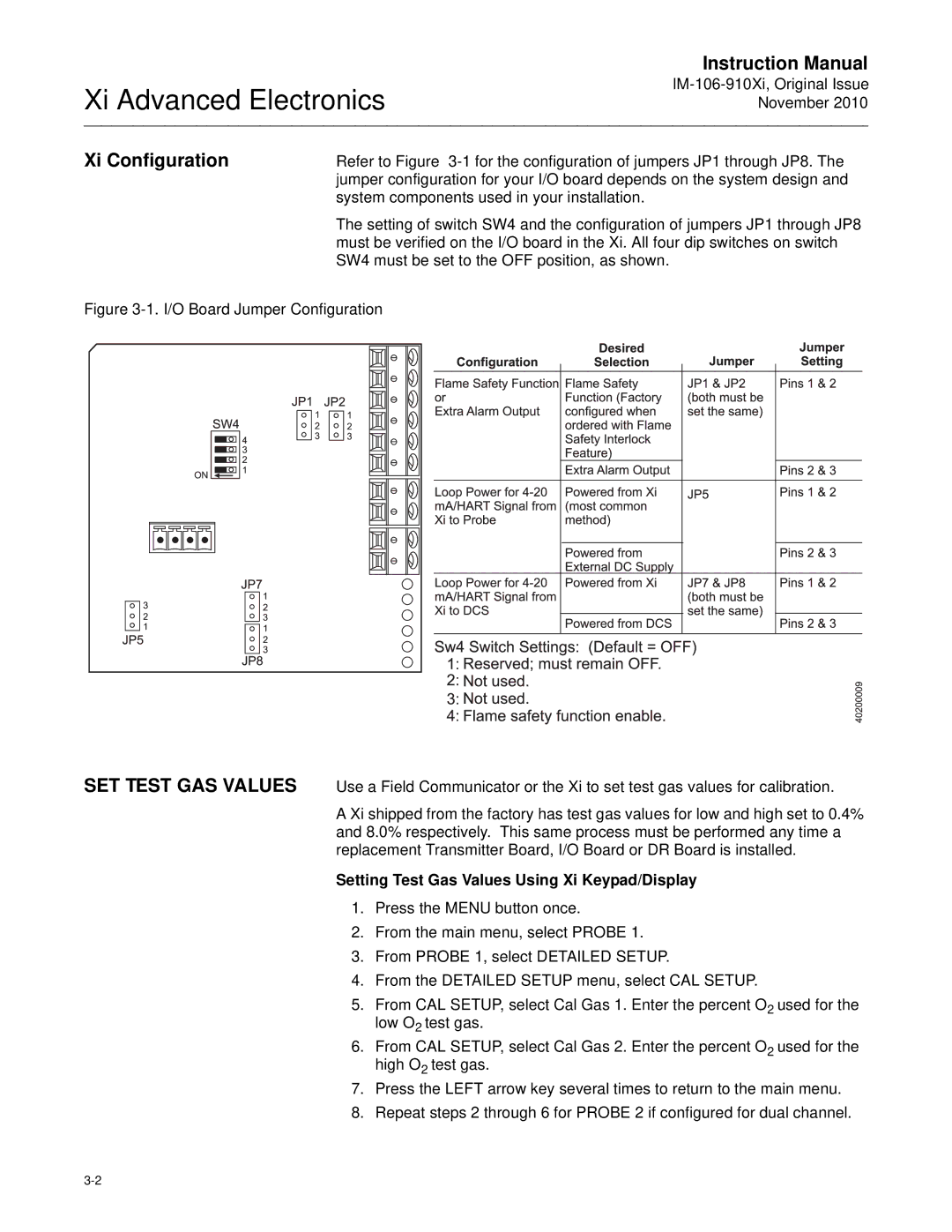
Refer to Figure
The setting of switch SW4 and the configuration of jumpers JP1 through JP8 must be verified on the I/O board in the Xi. All four dip switches on switch SW4 must be set to the OFF position, as shown.
Figure 3-1. I/O Board Jumper Configuration
SET TEST GAS VALUES
Use a Field Communicator or the Xi to set test gas values for calibration.
A Xi shipped from the factory has test gas values for low and high set to 0.4% and 8.0% respectively. This same process must be performed any time a replacement Transmitter Board, I/O Board or DR Board is installed.
Setting Test Gas Values Using Xi Keypad/Display
1.Press the MENU button once.
2.From the main menu, select PROBE 1.
3.From PROBE 1, select DETAILED SETUP.
4.From the DETAILED SETUP menu, select CAL SETUP.
5.From CAL SETUP, select Cal Gas 1. Enter the percent O2 used for the low O2 test gas.
6.From CAL SETUP, select Cal Gas 2. Enter the percent O2 used for the high O2 test gas.
7.Press the LEFT arrow key several times to return to the main menu.
8.Repeat steps 2 through 6 for PROBE 2 if configured for dual channel.