Instruction Manual
IM-106-910Xi, Original Issue November 2010
Xi Advanced Electronics
|
| PARAMETER |
|
|
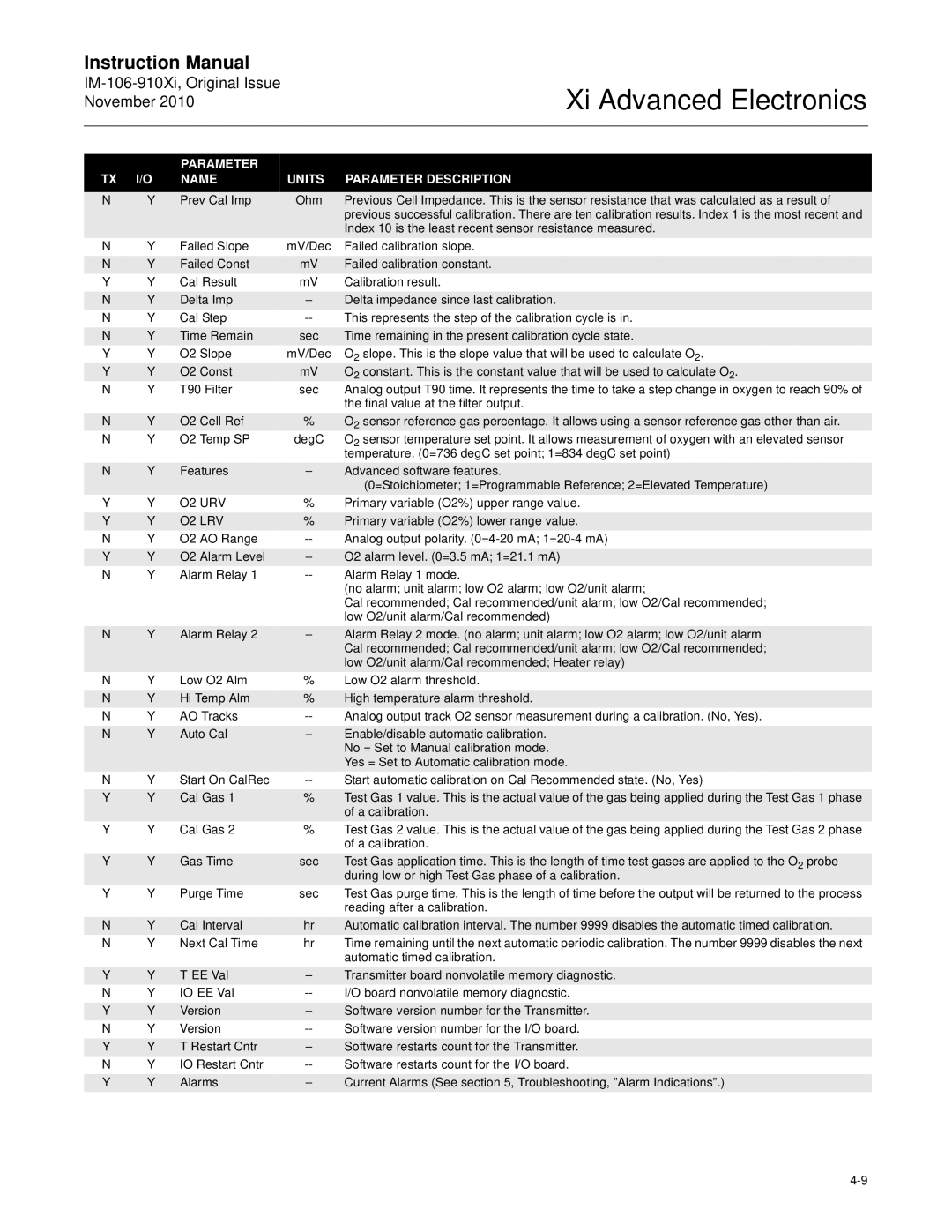
TX | I/O | NAME | UNITS | PARAMETER DESCRIPTION |
|
|
|
|
|
N | Y | Prev Cal Imp | Ohm | Previous Cell Impedance. This is the sensor resistance that was calculated as a result of |
|
|
|
| previous successful calibration. There are ten calibration results. Index 1 is the most recent and |
|
|
|
| Index 10 is the least recent sensor resistance measured. |
N | Y | Failed Slope | mV/Dec | Failed calibration slope. |
|
|
|
|
|
N | Y | Failed Const | mV | Failed calibration constant. |
Y | Y | Cal Result | mV | Calibration result. |
|
|
|
|
|
N | Y | Delta Imp | Delta impedance since last calibration. | |
N | Y | Cal Step | This represents the step of the calibration cycle is in. | |
|
|
|
|
|
N | Y | Time Remain | sec | Time remaining in the present calibration cycle state. |
Y | Y | O2 Slope | mV/Dec | O2 slope. This is the slope value that will be used to calculate O2. |
Y | Y | O2 Const | mV | O2 constant. This is the constant value that will be used to calculate O2. |
N | Y | T90 Filter | sec | Analog output T90 time. It represents the time to take a step change in oxygen to reach 90% of |
|
|
|
| the final value at the filter output. |
|
|
|
|
|
N | Y | O2 Cell Ref | % | O2 sensor reference gas percentage. It allows using a sensor reference gas other than air. |
N | Y | O2 Temp SP | degC | O2 sensor temperature set point. It allows measurement of oxygen with an elevated sensor |
|
|
|
| temperature. (0=736 degC set point; 1=834 degC set point) |
|
|
|
|
|
N | Y | Features | Advanced software features. | |
|
|
|
| (0=Stoichiometer; 1=Programmable Reference; 2=Elevated Temperature) |
Y | Y | O2 URV | % | Primary variable (O2%) upper range value. |
|
|
|
|
|
Y | Y | O2 LRV | % | Primary variable (O2%) lower range value. |
N | Y | O2 AO Range | Analog output polarity. | |
|
|
|
|
|
Y | Y | O2 Alarm Level | O2 alarm level. (0=3.5 mA; 1=21.1 mA) | |
N | Y | Alarm Relay 1 | Alarm Relay 1 mode. | |
|
|
|
| (no alarm; unit alarm; low O2 alarm; low O2/unit alarm; |
|
|
|
| Cal recommended; Cal recommended/unit alarm; low O2/Cal recommended; |
|
|
|
| low O2/unit alarm/Cal recommended) |
|
|
|
|
|
N | Y | Alarm Relay 2 | Alarm Relay 2 mode. (no alarm; unit alarm; low O2 alarm; low O2/unit alarm | |
|
|
|
| Cal recommended; Cal recommended/unit alarm; low O2/Cal recommended; |
|
|
|
| low O2/unit alarm/Cal recommended; Heater relay) |
N | Y | Low O2 Alm | % | Low O2 alarm threshold. |
|
|
|
|
|
N | Y | Hi Temp Alm | % | High temperature alarm threshold. |
N | Y | AO Tracks | Analog output track O2 sensor measurement during a calibration. (No, Yes). | |
|
|
|
|
|
N | Y | Auto Cal | Enable/disable automatic calibration. | |
|
|
|
| No = Set to Manual calibration mode. |
|
|
|
| Yes = Set to Automatic calibration mode. |
N | Y | Start On CalRec | Start automatic calibration on Cal Recommended state. (No, Yes) | |
|
|
|
|
|
Y | Y | Cal Gas 1 | % | Test Gas 1 value. This is the actual value of the gas being applied during the Test Gas 1 phase |
|
|
|
| of a calibration. |
Y | Y | Cal Gas 2 | % | Test Gas 2 value. This is the actual value of the gas being applied during the Test Gas 2 phase |
|
|
|
| of a calibration. |
|
|
|
|
|
Y | Y | Gas Time | sec | Test Gas application time. This is the length of time test gases are applied to the O2 probe |
|
|
|
| during low or high Test Gas phase of a calibration. |
Y | Y | Purge Time | sec | Test Gas purge time. This is the length of time before the output will be returned to the process |
|
|
|
| reading after a calibration. |
|
|
|
|
|
N | Y | Cal Interval | hr | Automatic calibration interval. The number 9999 disables the automatic timed calibration. |
N | Y | Next Cal Time | hr | Time remaining until the next automatic periodic calibration. The number 9999 disables the next |
|
|
|
| automatic timed calibration. |
|
|
|
|
|
Y | Y | T EE Val | Transmitter board nonvolatile memory diagnostic. | |
N | Y | IO EE Val | I/O board nonvolatile memory diagnostic. | |
|
|
|
|
|
Y | Y | Version | Software version number for the Transmitter. | |
N | Y | Version | Software version number for the I/O board. | |
|
|
|
|
|
Y | Y | T Restart Cntr | Software restarts count for the Transmitter. | |
N | Y | IO Restart Cntr | Software restarts count for the I/O board. | |
|
|
|
|
|
Y | Y | Alarms | Current Alarms (See section 5, Troubleshooting, ”Alarm Indications”.) | |
|
|
|
|
|