Xi Advanced Electronics
Instruction Manual
8.Connect two wires approximately 6" long each between the "HTR COM" and the "HTR NC" connections on the I/O Board and the "RELAY IN" connections on the AC Relay Board; observe polarity. See Figure
9.Connect the flame status indicator contact to the "DI+" and
10.Connect the AC input and output wiring to the Transmitter. See Figure
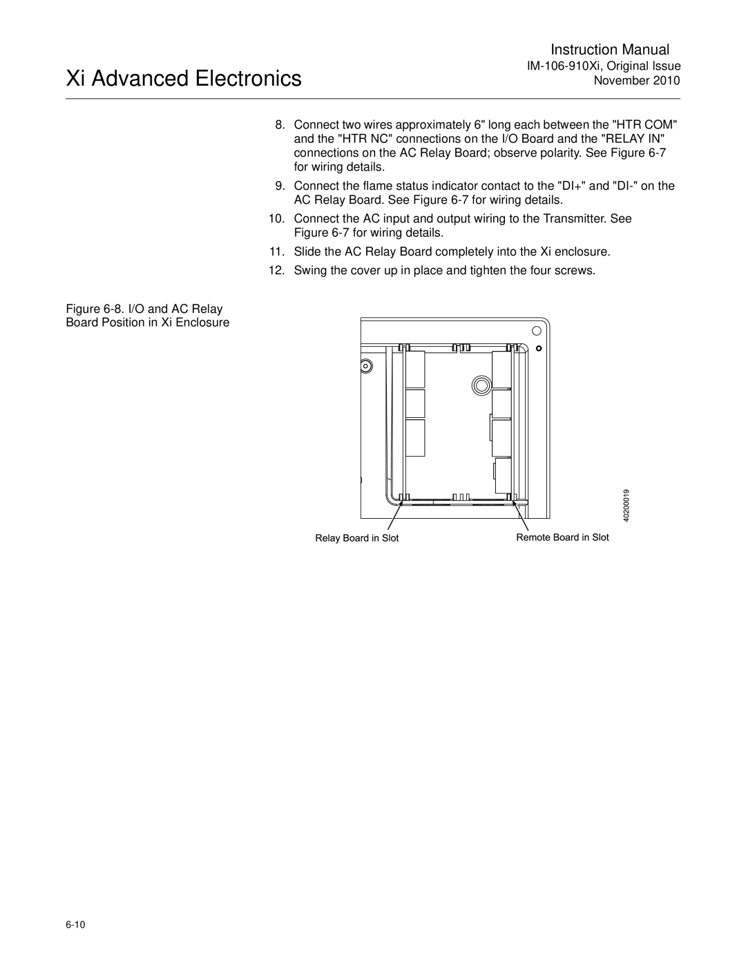
11.Slide the AC Relay Board completely into the Xi enclosure.
12.Swing the cover up in place and tighten the four screws.