TM-T81
Revision Sheet
Specification
TM-T81
Revisions Design Section Sheet Rev. No Document
Cover Rev Confidentiality General Contents
REV. Sheet
Changed Contents
Confidentiality Agreement
Epson Specification Standard
General Features
Confidential
Print Buffer-full Printing
Function 5 GS E pL pH fn a1 n1L n1H
FS g 1 m a1 a2 a3 a4 nL nH d1...dk
Function 48 GS H pL pH fn m d1 d2 d3 d4
GS 8 L p1 p2 p3 p4 m fn parameters
FS q n xL xH yL yH d1...dk1 ... xL xH yL yH d1...dkn
GS∗x y d1...dk
GS v 0 m xL xH yL yH d1...dk
Printing Specifications
General Specifications
Autocutter
Character Specifications
1 Character Size
Paper Roll Supply Device
Paper Specification
AF50KS-E
1 Specified Original Paper Type No. Single-color paper
Printing and Cutting Positions
Printable Area
Internal Buffer
1 Current Consumption Operating
Electrical Characteristics
2 Limitation of the Printing Length on Print Ratio
Reliability
EMI and Safety Standards Applied
EMI
Environmental Conditions
12.1 Operating Temperature and Humidity Range
Installation
Specifications
Configuration
Switching between online and offline
Interface 1 RS-232 serial interface
GS a
1 TM-T81 Printer Status and Signals
DLE ENQ 1 or DLE ENQ 2 commands
TM-T81 Printer Status and Signals
1.4 XON/XOFF transmit timing
2 XON/XOFF Transmit Timing
TXD RXD DSR DTR
Serial interface connection example
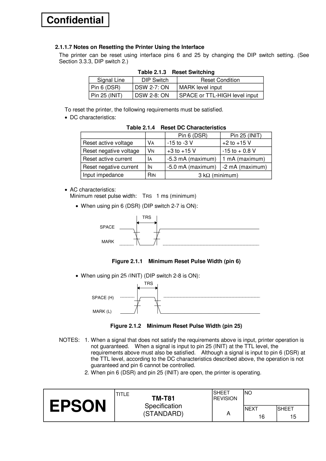
4 Reset DC Characteristics
Reset Switching
USB Universal Serial Bus Interface Outline
USB transmission specifications 1 USB function
Power Supply Connector
Connectors
1 Power Supply Connector Pin Assignments
GND Shell F.G
2 Drawer Kick-out Connector Pin Assignments
Drawer Kick-out Connector Modular Connector
4 Drawer Circuitry
Functions
List of Commands
FS g GS $ GS a GS D GS E GS H GS K GS L / GS 8 L
ESC a ESC c ESC d ESC p ESC t
GS \ GS a GS b GS f GS g GS h GS k GS r GS w
GS k GS ∗
Epson
Common to all pages International Character Set USA
Character Code Tables
HEX
0 PC437 USA, Standard Europe
1 Katakana
2 PC850 Multilingual
3 PC860 Portuguese
4 PC863 Canadian-French
5 PC865 Nordic
16 WPC1252
17 PC866 Cyrillic #2
18 PC852 Latin2
19 PC858 Euro
255 User-defined
USA
International Character Sets
Panel Buttons
Switches and Buttons Power Button
XON/XOFF DTR/DSR
DIP Switches
2 Transmission Speed
4 DIP Switch 2-3
DIP Switch
7 DIP Switch 2-3
USB interface specification DIP Switch
8 Types of the Customized Value
Customized value
1 Panel Switches and Indicators
Panel LED Indicators
Self-test
C D E F G H I J
Hexadecimal Dumping
NV Graphics Print Mode
1 Errors That Automatically Recover
Error Processing Error Types
2 Errors That Can Possibly Recover
Unrecoverable Errors
Printer Operation When an Error Occurs
CPU
Print Buffer-full Printing
Cover Open Sensor
External Dimensions and Mass
Case Specifications
Color
External Appearance
Options and Consumables
Standard Accessories
Options
Consumables
Command Notation
Commands
Explanation of Terms
MSB LSB
Ascii
Control Commands
Ascii Can
DLE EOT n
Ascii DLE EOT
Epson
Epson
Ascii DLE ENQ
DLE ENQ n
Ascii DLE DC4
DLE DC4 fn m t fn =
Fn =
DLE DC4 fn a b fn =
Fn =
DLE DC4 fn d1…d7
ESC SP n
D1…d7
ESC ! n
ESC % n
ESC $ nL nH
ESC & y c1 c2 x1 d1 Dy ⋅x1 Xk d1 Dy ⋅xk
Dy ⋅x1 Dy ⋅xk
ESC − n
ESC ∗ m nL nH d1...dk
D1...dk
ESC = n
ESC 3 n
ESC ? n
ESC E n
ESC D n1...nk NUL
N1...nk
ESC J n
ESC G n
ESC R n
ESC M n
ESC V n
ESC T n
Dx L Dx H Dy L Dy H
ESC \ nL nH
ESC c 4 n
ESC a n
ESC c 5 n
ESC p m t1 t2
ESC d n
ESC n
FS g 2 m a1 a2 a3 a4 n L n H
FS g 1 m a1 a2 a3 a4 n L n H d1...dk
GS $ nL nH
GS ! n
Test pattern
GS a pL pH n m
Hexadecimal dump print
Printer status print
GS D pL pH m a1 b1...ak bk
Function 1 GS E p L p H fn d1 d2 Fn =
GS E pL pH fn parameters
Format
GS E pL pH fn
Function 5 GS E p L p H fn a1 n1 L n1 H...ak nk L nk H
Function 2 GS E p L p H fn d1 d2 d3 Fn =
N1 L N1 H ... ak nk L nk H
Type of customized value
Epson
Function 11 GS E pL pH fn a d1...dk fn =
Function 6 GS E p L p H fn a Fn =
D1 ... dk
GS H pL pH fn parameters
Function 12 GS E p L p H fn a Fn =
Function 48 GS H p L p H fn m d1 d2 d3 d4
Function 50 GS K p L p H fn m Fn =
GS K pL pH fn parameters
Format Function No Function name
Select the print speed
GS 8 L
GS L
GS L pL pH m fn
Function 50 GS L p L p H m fn Fn = 2
Function 48 GS L p L p H m fn Fn = 0
Function 64 GS L p L p H m fn d1 d2 Fn =
Function 51 GS L p L p H m fn Fn = 3
Function 65 GS L p L p H m fn d1 d2 d3
Function
Function 66 GS L p L p H m fn kc1 kc2 Fn =
Kc1 Kc2
Vertical direction Horizontal direction 180 dpi 90 dpi
Function 69 GS L p L p H m fn kc1 kc2 x y
Bx , by
P H m fn a bx by c x L x H y L y H d1...dk
GS k pL pH cn fn parameters
Function 066 GS k p L p H cn fn n Cn = 48 , fn =
Function 065 GS k p L p H cn fn n Cn = 48 , fn =
Function 068 GS k p L p H cn fn n Cn = 48 , fn =
Function 067 GS k p L p H cn fn n Cn = 48 , fn =
Function 069 GS k p L p H cn fn m n Cn = 48 , fn =
Function 080 GS k p L p H cn fn m d1 … dk Cn = 48 , fn =
Function 070 GS k p L p H cn fn m Cn = 48 , fn =
D1…dk
Function 082 GS k p L p H cn fn m Cn = 48 , fn =
Function 081 GS k p L p H cn fn m Cn = 48 , fn =
P H cn fn m
Function 167 GS k p L p H cn fn n Cn = 49 , fn =
Function 165 GS k p L p H cn fn n1 n2 Cn = 49 , fn =
N2 =
Function 180 GS k p L p H cn fn m d1 … dk Cn = 49 , fn =
Function 169 GS k p L p H cn fn n Cn = 49 , fn =
Function 182 GS k p L p H cn fn m Cn = 49 , fn =
Function 181 GS k p L p H cn fn m Cn = 49 , fn =
GS / m
GS ∗ x y d1...dk
= x ⋅ y ⋅
GS H n
GS B n
Epson
GS I n
GS P x y
GS L nL nH
GS V m B GS V m n
GS \ nL nH
GS W nL nH
GS r t m
GS a n
Name Turn smoothing mode on/off Format
GS g 0 m nL nH
GS f n
L n H
GS g 2 m nL nH
D1...dn
GS k m d1...dk NUL GS k m n d1...dn
Bar code system Range of n Range of d
= 11 ≤ d ≤ 57 where d1 = JAN13 / EAN13 = 12
= 11
= 7
GS r n
GS w n
ESC
Obsolete Commands
ESC m
6DF
ESC u n
X H y L y H d1...dk1...x L x H y L y H d1...dkn
FS p n m
GS v 0 m x L x H y L y H d1...dk
Table A.1 Paper Feeding Amount
Appendix a Miscellaneous Notes
App.3 App.2
Other Notes
Replacing the Paper Roll
Appendix B Paper Roll Setup
Appendix C Recovery from the Auto Cutter Error
Figure D.1 Near-end Adjusting Position
Table D.1 Adjustment Positions
Figure E.1 Print Head Thermal Elements
Appendix E Print Head Cleaning
Appendix F Notes on Using the Drawer KICK-OUT Connector
Ii. For DLE DC4
T1 ⋅ 2ms
Return
∗WAIT300MS
Power off procedure by the host
About updating the maintenance counter
Figure I-1 Slant of the Print
Appendix H Notes on Printing 2-DIMENSIONAL Code
END
Appendix J Notes on Using the ASB Status