Rear Panels
![]() 10A
10A
1 | 2 | 3 | 4 | S/N XXXXXXXXX E0000 0408 |
![]() 5
5
50/60 Hz
ALARM
![]() TOTAL LOAD 10A MAX
TOTAL LOAD 10A MAX
LAN
1 |
|
| 2 |
| 3 | 4 |
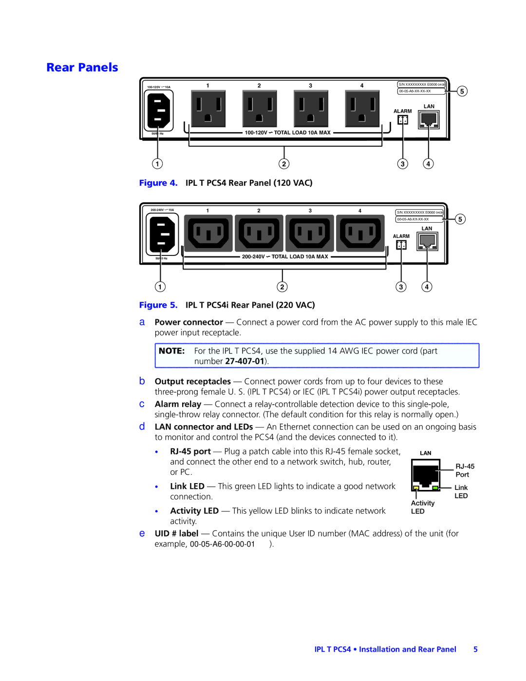
Figure 4. IPL T PCS4 Rear Panel (120 VAC) |
|
|
| |||
1 | 2 | 3 | 4 | S/N XXXXXXXXX E0000 0408 | ||
| ||||||
![]() 5
5
LAN
ALARM
50/60 Hz
![]() TOTAL LOAD 10A MAX
TOTAL LOAD 10A MAX
1 | 2 | 3 | 4 |
Figure 5. IPL T PCS4i Rear Panel (220 VAC)
APower connector — Connect a power cord from the AC power supply to this male IEC power input receptacle.
![]() NOTE: For the IPL T PCS4, use the supplied 14 AWG IEC power cord (part
NOTE: For the IPL T PCS4, use the supplied 14 AWG IEC power cord (part ![]() number
number
BOutput receptacles — Connect power cords from up to four devices to these
CAlarm relay — Connect a
DLAN connector and LEDs — An Ethernet connection can be used on an ongoing basis to monitor and control the PCS4 (and the devices connected to it).
•
•Link LED — This green LED lights to indicate a good network connection.
•Activity LED — This yellow LED blinks to indicate network activity.
LAN
Port
Link |
LED |
Activity
LED
EUID # label — Contains the unique User ID number (MAC address) of the unit (for example,
IPL T PCS4 • Installation and Rear Panel | 5 |