Setting Up the LAN Port
LAN Port Cabling
•For
•For
•Use a
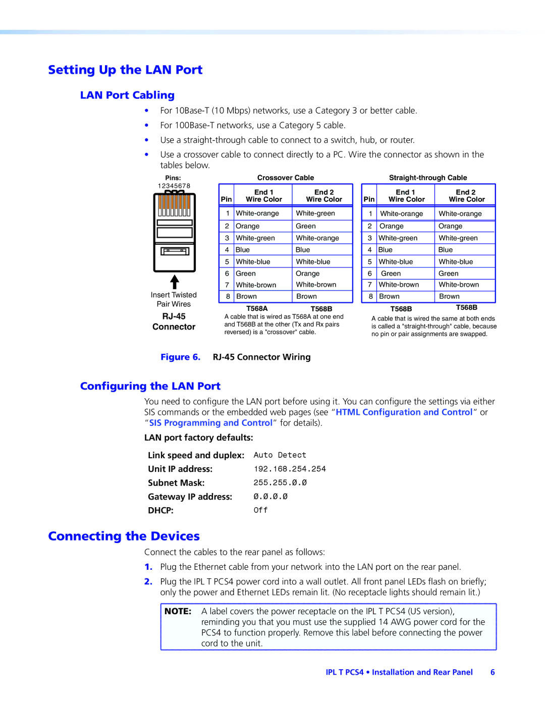
•Use a crossover cable to connect directly to a PC. Wire the connector as shown in the tables below.
Pins:
12345678
Insert Twisted
Pair Wires
RJ-45
Connector
Crossover Cable
| End 1 | End 2 |
Pin | Wire Color | Wire Color |
|
|
|
|
|
|
1 | ||
|
|
|
2 | Orange | Green |
|
|
|
3 | ||
|
|
|
4 | Blue | Blue |
|
|
|
5 | ||
|
|
|
6 | Green | Orange |
7 | ||
|
|
|
8 | Brown | Brown |
|
|
|
| T568A | T568B |
A cable that is wired as T568A at one end and T568B at the other (Tx and Rx pairs reversed) is a "crossover" cable.
Straight-through Cable
Pin | End 1 | End 2 |
Wire Color | Wire Color | |
|
|
|
|
|
|
1 | ||
|
|
|
|
|
|
2 | Orange | Orange |
|
|
|
3 | ||
|
|
|
4 | Blue | Blue |
|
|
|
5 | ||
|
|
|
6 | Green | Green |
|
|
|
7 | ||
|
|
|
8 | Brown | Brown |
|
|
|
| T568B | T568B |
A cable that is wired the same at both ends is called a
Figure 6.
Configuring the LAN Port
You need to configure the LAN port before using it. You can configure the settings via either SIS commands or the embedded web pages (see “HTML Configuration and Control” or “SIS Programming and Control” for details).
LAN port factory defaults:
Link speed and duplex: | Auto Detect |
Unit IP address: | 192.168.254.254 |
Subnet Mask: | 255.255.0.0 |
Gateway IP address: | 0.0.0.0 |
DHCP: | Off |
Connecting the Devices
Connect the cables to the rear panel as follows:
1.Plug the Ethernet cable from your network into the LAN port on the rear panel.
2.Plug the IPL T PCS4 power cord into a wall outlet. All front panel LEDs flash on briefly; only the power and Ethernet LEDs remain lit. (No receptacle lights should remain lit.)
![]() NOTE: A label covers the power receptacle on the IPL T PCS4 (US version),
NOTE: A label covers the power receptacle on the IPL T PCS4 (US version), ![]() reminding you that you must use the supplied 14 AWG power cord for the
reminding you that you must use the supplied 14 AWG power cord for the
PCS4 to function properly. Remove this label before connecting the power cord to the unit.
IPL T PCS4 • Installation and Rear Panel | 6 |