System 7SC
System Switcher
Instrucciones de seguridad Español
Safety Instructions English
Consignes de Sécurité Français
Sicherheitsanleitungen Deutsch
Table of Contents
Table of Contents, cont’d
System 7SC Table of Contents Iii
Iv System 7SC Table of Contents
One
Typical System 7SC application
What is the System 7SC?
About this Manual
About the System 7SC
Controlling the switcher and an A/V system
MHz -3 dB video bandwidth Configurable video inputs
Features and Options
Features
Options and accessories
Introduction, cont’d
Two
Rack mounting
Mounting the Switcher
Cabling and Panel Views
Tabletop use
System 7SC Front Panel
Front panel inputs
Power, video, and audio conections
Rear panel inputs
Outputs
Captive screw connector wiring for rear panel audio inputs
Audio inputs
RGB
Control device connections
IR communications port IR Comm
For the IR Emitter only
IR Communications port wiring options
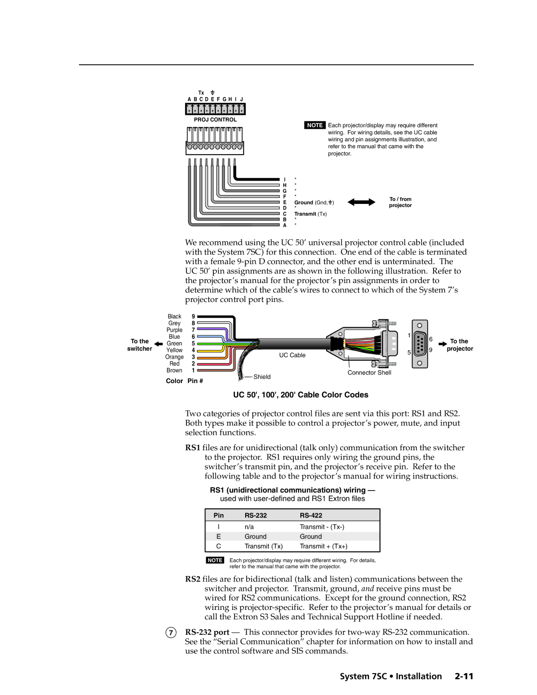
UC 50, 100, 200 Cable Color Codes
Connecting and Slaving a Switcher
System 7SC Rear Panel
System 7SC master connected to a slaved switcher
Labeling Buttons on the System 7SC and SCPs
Example of input numbering with a six-input slaved switcher
System 7SC button label screen SCP 200 button label screen
Installing the software
Using the software
Button-Label Generator software
Installing labels in the System 7SC’s buttons
Three
System 7SC Operation and Configuration
Front Panel Features and Basic Operation
Control features
Display Mute button
Display Power button
Mode button
Adjustment features
Operation and Configuration, cont’d
Display command indicator LEDs
Input selection features
Miscellaneous features
Example
IR and RS-232 Projector Control
Projector control memory
Projector control memory usage
Optimizing the System
Setting up a DVD source
Menu overview
Menus, Configuration, and Adjustments
Moving through menus by using front panel controls
Default menus
Scaler Polarity +/V+
Switcher Setup/Configuration
Scaler Polarity sync polarity
Scaler Rate resolution and refresh rate
RGB Delay Triple-Action Switching
Scaler Sync RGB format
Edge Smoothing
Add Slave slaving switchers
System 7SC with a slaved switcher
Input Configuration signal format
Audio/Video Adjustments
Size Input
Blank Input blanking adjustment
Audio Level
Image Size
Navigating through the IR Learning Configuration menu
IR Learning Configuration
Clearing IR commands from a button’s memory
Clearing IR commands from memories
Initiating IR learning
Initiating IR learning
Information/System Options
Image adjustments
Reset to Default clearing settings and adjustments
Global system reset
Centering
Executive mode front panel lockout
Input you wish to adjust
SCP control pads
Remote Control of the System 7SC
Enabling and disabling executive mode
Selecting an input
IR 701 infrared remote control
Four
RS-232 Programmer’s Guide
Host-to-switcher communications
Switcher-initiated messages
Error responses
Ascii to Hex conversion table
Using the command/response tables
Symbol definitions
Command Ascii Command Response Additional description
Tint
Video configuration
Detail mode
Color
Top blanking
Image size
Horizontal size
Vertical size
Firmware version, part number & information requests
Executive mode front panel lockout
Zap reset to default settings
Room relays
Command Ascii Command Response Values
Delay times
Scaler settings
Miscellaneous settings
Audio settings
IR-related settings
Send/receive a flag parameter block
Command Hex. command Response Additional description
Send/receive data to/from page 0 memory
Send/receive data to/from page 1 memory
Control Software for Windows
Installing the software
Using the control program
Mini Mode
Configuration
User Mode
Special features
Real Time Adjustments
Projector Driver
Room & Misc. Options
Saving and restoring configurations
Key to file names File name Description
Using the help program
Downloading and using projector drivers
AAppendix a
System 7SC Reference Material
Specifications
Sync
Reference Material, cont’d
Accessories Part number
Part Numbers and Accessories
Accessories
Included parts Replacement Part number
Align Notches
Firmware Upgrade Installation
System 7SC Reference Material
Glossary
Asia Japan
FCC Class a Notice Extron’s Warranty
Extron Electronics, USA