Installation, cont’d
3.For a System 8 PLUS or System 10 Plus switcher, set the slaved switcher to master mode. On the slaved System 8 PLUS or System 10 Plus switcher, locate the Address DIP switches on the back panel, and set switches #1, 2, 3, 4, and 5 up.
4.Power on the slaved switcher and the System 7SC.
5.From within Add Slave? in the System 7SC’s Switcher Setup/Configuration menu, select the slave switcher type and size. See chapter three, “Operation and Configuration”, for information on using the menus.
6.Use the front panel buttons and menus or the host computer to configure the video formats for the slaved switcher’s inputs. See chapter 3, “Operation and Configuration”, for details on how to configure inputs. The inputs of the slaved switcher do not have to all be the same video signal type. Each input can be configured in the System 7 for a different signal type (RGB, component video,
Once the slaved switcher is connected and configured, its inputs will be the
System 7’s first inputs (input 1 through input 2, 4, 6, 8, or 10). Input 2 of the
System 7 becomes the next input (input 2, 5, 7, 9, or 11).
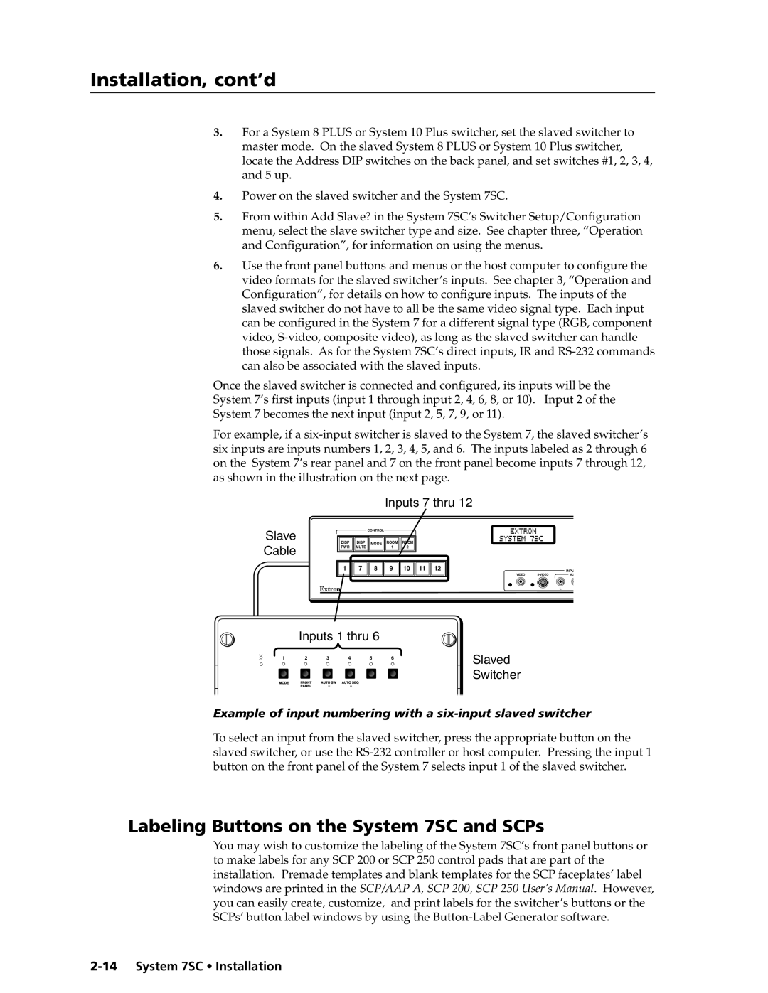
For example, if a
Inputs 7 thru 12
Slave Cable
CONTROL
DISP | DISP | MODE | ROOM | ROOM |
PWR | MUTE |
| 1 | 2 |
1 | 7 | 8 | 9 | 10 | 11 | 12 |
INPU
VIDEO | AU |
L
Inputs 1 thru 6
1 | 2 | 3 | 4 | 5 | 6 |
Slaved Switcher
Example of input numbering with a six-input slaved switcher
To select an input from the slaved switcher, press the appropriate button on the slaved switcher, or use the
Labeling Buttons on the System 7SC and SCPs
You may wish to customize the labeling of the System 7SC’s front panel buttons or to make labels for any SCP 200 or SCP 250 control pads that are part of the installation. Premade templates and blank templates for the SCP faceplates’ label windows are printed in the SCP/AAP A, SCP 200, SCP 250 User’s Manual. However, you can easily create, customize, and print labels for the switcher’s buttons or the SCPs’ button label windows by using the