Reference Material, cont’d
Firmware Upgrade Installation
In some cases the System 7SC’s firmware may require replacement with an updated version. The
Changes to firmware must be performed by authorized service personnel only. Some System 7SC firmware updates must be performed at the Extron factory.
Follow these steps to replace firmware in the System 7SC.
1.Disconnect the AC power cord from the System 7SC to remove power from the unit.
To prevent electric shock, always unplug the System 7SC switcher from the AC power source before opening the enclosure.
2.Remove the switcher from the rack, wall or furniture.
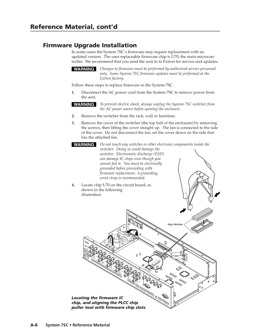
3.Remove the cover of the switcher (the top half of the enclosure) by removing the screws, then lifting the cover straight up. The fan is connected to the side of the cover. Do not disconnect the fan; set the cover down on the side that has the attached fan.
Do not touch any switches or other electronic components inside the switcher. Doing so could damage the
switcher. Electrostatic discharge (ESD) can damage IC chips even though you cannot feel it. You must be electrically grounded before proceeding with firmware replacement. A grounding wrist strap is recommended.
4.Locate chip U70 on the circuit board, as shown in the following
illustration.
Align Notches
Anaheim, | CA |
|
|
| |
100- |
|
|
240 |
|
|
1.3A M50/60 | Hz | |
AX. | ||
RR
![]()
G/Y
![]() VID
VID
B/C
L![]()
1 R
H/HV![]()
![]()
V
1 ![]()
L![]()
2 R
L
|
| R |
|
| |
|
| G/Y |
|
| VID |
|
| B/C |
| AU | B- |
| Y | |
|
| DIO |
3 | R |
|
|
|
IN
L
| H/HV |
|
|
|
|
|
| R |
|
| V |
|
| |
|
|
|
| |
2 |
| G/Y |
| |
|
|
|
| |
|
|
| VID |
|
|
|
| B/C |
|
4 |
|
|
| |
R |
|
|
| |
|
|
|
| |
| L | 5 | R |
|
|
|
| ||
|
|
| L | 6 |
|
|
|
| |
INPUTS | ||
H/HV |
|
|
V |
|
|
3 |
|
|
A | UD |
|
F | IO | |
IXED | ||
R![]()
![]()
L ![]()
![]() R
R
| R |
| |
| G/Y |
| VID |
O | B/C |
B- | |
| UT Y |
VAR | |
| IABLE |
L![]()
![]()
R
H/HV |
| |
R |
| |
| ||
V | H/HV | |
4 | ||
| ||
G/Y |
| |
VID |
| |
| V | |
B/C | 5 | |
|
E | SCP/AAP |
|
| ||
| D | B |
| CONTROL | |
|
|
| A E | D | |
| 1 |
|
|
| B A |
2
| R |
| |
|
| ||
| G/Y |
| |
| VID |
| |
| B/C | 6 | |
A |
| ||
B C |
|
| |
| D E |
| |
|
| 1 | |
IR |
|
| |
TRANSPORT |
| ||
H/HV |
| |
V |
| R |
|
| |
2 3 | 4 5 |
|
| 6 7 | |
C |
| |
|
| |
ONT |
| |
| ACT | CLO |
|
| SU |
|
| RE |
G
B
RGB |
|
|
|
| |
A | B C |
|
|
|
|
| D E |
|
|
| |
|
| A | B C |
| |
|
|
|
| ||
| RELAY 1 |
| D E | ||
|
|
| |||
OUTPUTS |
H/HV |
V |
Locating the firmware IC
chip, and aligning the PLCC chip puller tool with firmware chip slots
RELAY 2 |
D |
| E | D | C |
|
|
ISPLAY | PW |
|
| B |
| |
SEN |
|
|
| A | ||
SOR R |
|
|
|
| ||
IR | CO |
| MM |
A |
|
|
|
| RS- |
|
B | C |
| 232 |
| ||
|
| D | E F |
| ||
|
|
|
|
| ||
|
|
|
|
|
| |
|
| P |
|
| G H | IJ |
|
| ROJ | ||||
|
|
|
| |||
|
|
|
|
| CO |
|
|
|
|
|
| NTR |
|
|
|
|
|
| OL | |