Input selection features
8Input selection buttons — These buttons correspond to the seven inputs. When you select an input, the corresponding button lights and remains lit until another input is selected or power is removed. The factory default (and reset default) is for input one to be active. However, the last input selected before power down will be active when the switcher is powered up.
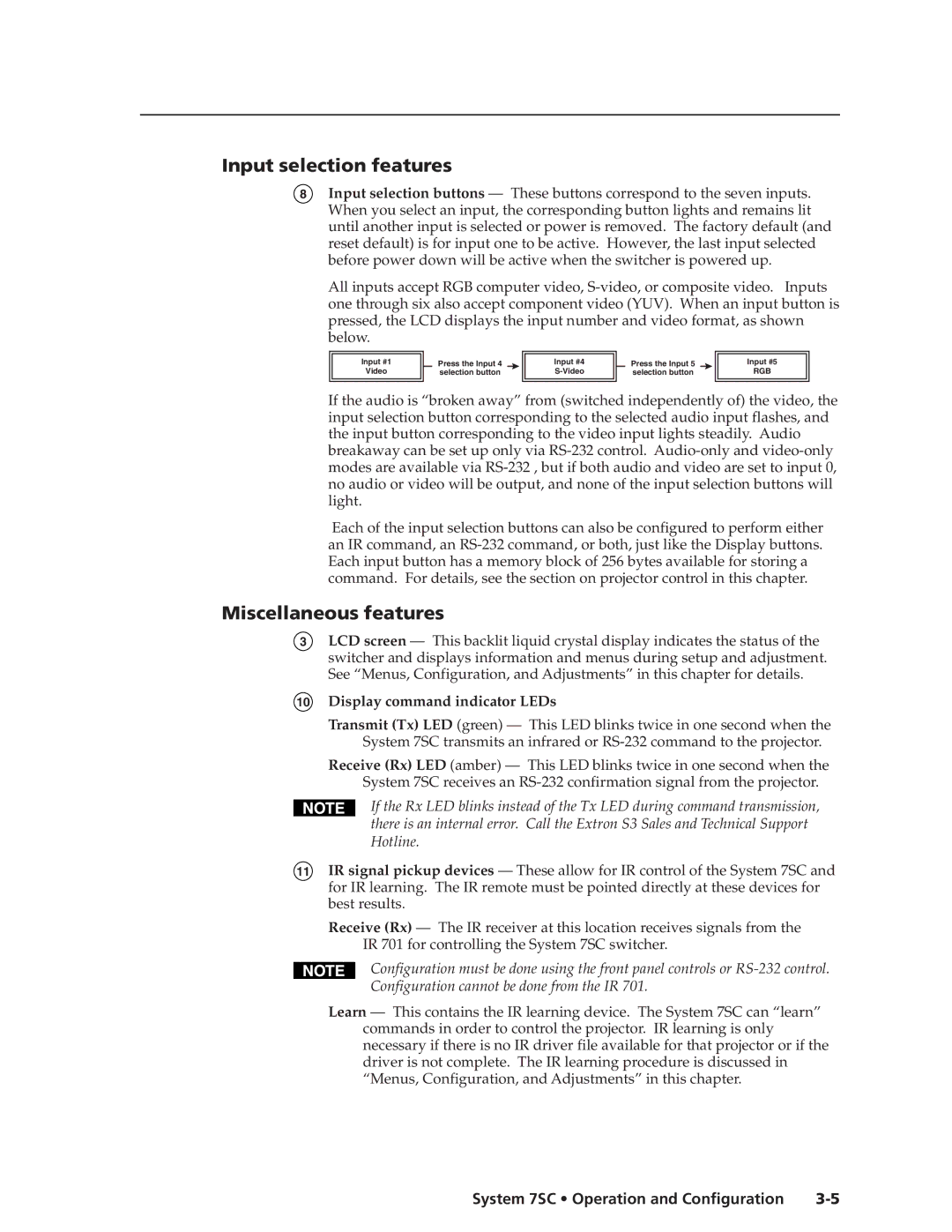
All inputs accept RGB computer video,
Input #1
Video
Press the Input 4 selection button
Input #4
Press the Input 5 selection button
Input #5
RGB
If the audio is “broken away” from (switched independently of) the video, the input selection button corresponding to the selected audio input flashes, and the input button corresponding to the video input lights steadily. Audio breakaway can be set up only via
Each of the input selection buttons can also be configured to perform either an IR command, an
Miscellaneous features
3LCD screen — This backlit liquid crystal display indicates the status of the switcher and displays information and menus during setup and adjustment. See “Menus, Configuration, and Adjustments” in this chapter for details.
10Display command indicator LEDs
Transmit (Tx) LED (green) — This LED blinks twice in one second when the System 7SC transmits an infrared or
Receive (Rx) LED (amber) — This LED blinks twice in one second when the System 7SC receives an
If the Rx LED blinks instead of the Tx LED during command transmission, there is an internal error. Call the Extron S3 Sales and Technical Support Hotline.
11IR signal pickup devices — These allow for IR control of the System 7SC and for IR learning. The IR remote must be pointed directly at these devices for best results.
Receive (Rx) — The IR receiver at this location receives signals from the IR 701 for controlling the System 7SC switcher.
Configuration must be done using the front panel controls or
Configuration cannot be done from the IR 701.
Learn — This contains the IR learning device. The System 7SC can “learn” commands in order to control the projector. IR learning is only necessary if there is no IR driver file available for that projector or if the driver is not complete. The IR learning procedure is discussed in “Menus, Configuration, and Adjustments” in this chapter.
System 7SC • Operation and Configuration |