Part Number L000307
Revision Control Date Document Title Number
Restricted USE only
HDP800 Series Input Card Accepted Encoding Lamination
Reviewing the HDP800 Series Printers Overview table
Capacity
Modules
Manual Description
How to use the manual
Exposed to static electricity discharges
Safety Messages review carefully
To prevent equipment or media damage, always wear an
To prevent equipment or media damage, always remove
HDP 800 Series Card Printer/Encoders Overview
Reviewing the HDP 800 Series Block Diagram
Step Process
Reviewing HDP 800 Series Card Printer Sequence of Operations
Reviewing HDP 800 Series Card Printer Sequence of Operations
Reviewing HDP 800 Series Card Printer Sequence of Operations
Sensor is activated. All off
Sensor
Reviewing the Lamination Module Sequence of Operations
Reviewing the Lamination Module Sequence of Operations
Reviewing Lamination Module Boot up Sequence
Table of Contents
Restricted USE ONLYFargo Electronics, Inc
Card Lamination Module
Restricted USE ONLYFargo Electronics, Inc
Cleaning
Restricted USE ONLYFargo Electronics, Inc
LCD On-Line Menu Navigation
Glossary of Terms Index Appendix a Engineering Drawings
Appendix B Technical Updates 535 Appendix C Miscellaneous
Specifications
Agency Listings
Regulatory Compliances
Technical Specifications
HDP820/820-LC
HDP825/825-LC
Technical Specifications
Technical Specifications
HDP820-LC/825-LC 87 lbs./39.5kg
Function Description
Functional Specifications
Component Description
Component Description
On the next
Softkey Buttons
Print Station Transfer Station
Component Description
Component Description
Refer to the previous table
Printer Components LCD and Softkey Control Pad
Printer Components LCD and Softkey Control Pad
Lamination Module. See Card Lamination Module on
Pause
Component Description Cancel
Printer Components LCD and Softkey Control Pad
Printer Components LCD and Softkey Control Pad
Printer Components Centronics-Type Parallel Interface
Printer Components Print Ribbons
Type Description
Printer Components Blank Cards
Printer Components Card Input Hopper HDP820/820-LC
Printer Components Card Input Hopper HDP825/825-LC
Printer Components Card Output Hopper
Printer Components Lamination Roller
Reviewing the Card Lamination Module
Component Description Reference
Reviewing the Lamination Top Cover and Station
Reviewing the Securing Latches and Lamination LED Light
Solid Green light Indicates the Card
Fast Flashing Green light Indicates
Component Description Reference Cancel
Reviewing the Cancel button
Component Description Reference Resume
Reviewing the Resume pause button
Reviewing the Rejection Card Hopper and Card Output Hopper
Term Description Reference
Reviewing the Module and Printer interaction
Reviewing the Module and LCD Display interaction
Target Temperature If a print job is
Reviewing the Module’s Programmed Default Temperature
Alternate with LAM Temp current
Initial Heating Process The initial
New Temperature Settings Once
Reviewing the Laminator Temperature Adjustment
Automatic Reset Whenever
Consistent Temperature
Term Description Cross Reference
Reviewing the Overlaminates
Thermal Transfer Film The Thermal
PolyGuard Overlaminate PolyGuard
Reviewing the Overlaminate Design
Reviewing the CR-90or CR-100Patch Size
Message Cause Solution
LCD/SmartGuard Messages
Reviewing LCD Messages
Dram
Reviewing LCD Messages
Fpga
See Card Feeding Errors
See Resolving the Temperature
See the Resolving the Failed
See the Resolving the Print
See the Printing a Test Image
Feeding problem procedure
Reviewing SmartGuard Error and Status Messages
Restricted USE only
Communications Errors
Resolving the Communication Errors
Step Procedure
Step
Resolving the Communication Errors
Cause communications errors
Resolving the Upgrade Failed error
Firmware Errors
Resolving an Upgrade Failed error
Resolving the Card Feeding problem HDP820/820-LC
Card Feeding Errors
Resolving a Card Feeding problem HDP820/820-LC
30mil
60mil
Clean the Cleaning Rollers
Resolving the Card Feeding Errors HDP825/825-LC
Resolving the Card Feeding Errors HDP825/825-LC
Insert cards neatly stacked
Resolving the jammed Cards on the Flipper Table
Resolving the stalled Cards on or at the Feed Rollers
Resolving the Flipper Alignment Error Message
Step
Resolving the Card Jam Error Message
Resolving the Card Jam Lam Error Message
Magnetic Encoding Errors
Resolving the No ENC Response Error Message
Resolving the No Magnetic Encoder Error Message
Resolving the Failed Magnetic Encode Error Message
Reset power on the Printer to clear any error messages
Towards the back of the Printer
Sending the Track Information procedure in ,
Resolving the Job Mismatch error
Card Encoding Errors
Flipper Offset may need to be adjusted
Resolving the No Smart Encoder Error Message
Resolving the No Prox Encoder Error Message
Resolving the Failed Smart Encode Error Message
Resolving the Ribbon Alignment Error Message
Printing Process Errors
Resolving the Print Ribbon Jam
Resolving the Print Ribbon Error Message
Resolving the Wrong Print Ribbon Error Message
Resolving the Print Ribbon Out Error Message
Resolving the Headlift Error Message
Resolving the Unknown Ribbon Type Error Message
Resolving the Printer pausing between Panels problem
Resolving the Printer Open Error Message
Resolving the Printhead Temp Error Message
Resolving the Upper and Lower Film errors
Transfer Process Errors
Resolving the Upper and Lower Film errors
Resolving the Film Sensor errors
Resolving the Film Sensor errors
Resolving the Film Sensor errors
Resolving the Film Sensor errors
Resolving the Transfer Cooling error
Resolving the Card Jam Error Message
Resolving the Transfer Lift Error Message
Resolving the Temperature Timeout Error Message
Resolving the Output Stacker errors
Resolving the Overlaminate Jam
Card Lamination Errors
Resolving the Overlaminate Jam
Select MENU, Setup Printer and Lamination TOF
Resolving the Card Lamination Placement errors
Resolving the Lam Error/Out Error Message
Resolving the Lam Error/Out Error Message
106
Check the Lamination Temperature
Resolving the Pixel failure problems
Diagnosing the Image Problems
Resolving the Pixel failure problems
Resolving the Card surface debris problems
Resolving the Card surface debris problems
Clean the Platen Roller
Resolving the incorrect Image Darkness problems
Resolving the incorrect Image Darkness problems
Resolving the Ribbon wrinkle problems
Resolving the Ribbon wrinkle problems
Resolving the excessive Resin Printing problems
Resolving the incomplete Resin Printing problems
Resolving the HDP Film wrinkle problems
Resolving the HDP Film wrinkle problems
Resolving the incomplete Transfer problems
Resolving an incomplete transfer on the leading edge problem
Resolving the Image Placement problems
Resolving the Image Placement problems
Select Printing Preferences
Select Document Defaults
126
Resolving the poor Image Quality problems
Resolving the Image washout on Film problems
Resolving the Registration problems
Resolving the Registration problems
Resolving the Card Skewed Image problems
Reviewing the Gray/Align YMC/K Self-Test
Printing a Test Image
Reviewing the Color Bars YMC Self-Test
Reviewing the Color/Resin Ymck Self-Test
Reviewing the Magnetic Test option
Reviewing the Card Count Self-Test
Reviewing the Lamination Color/Resin YMCK+L Self-Test
Card Lamination Module
Opening the Card Lamination Module
Opening the Card Lamination Module
139
Loading the Overlaminate
Take-Up Roll Supply Roll
Loading the Overlaminate
142
Adjusting the Card Flattener
Adjusting the Card Lamination Module
Adjusting the Card Flattener
Blank Card Card Flipping Mechanism
Adjusting the Card Guide Rail
Adjusting the Card Guide Rail
147
010/.25mm
Internal Card Guide Blank Card Screws
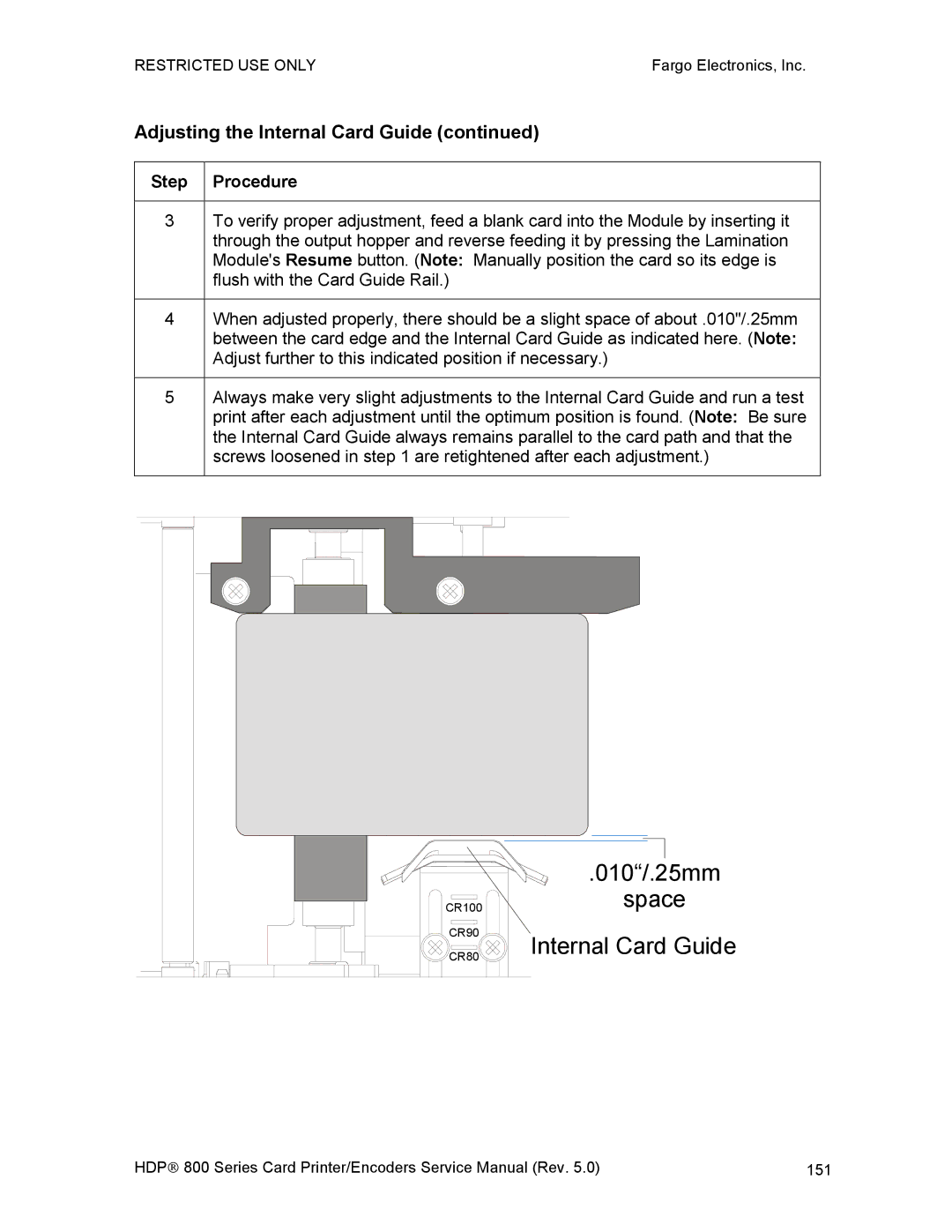
Adjusting the Internal Card Guide
Adjusting the Internal Card Guide
010/.25mm
Attaching the Card Lamination Module
Attaching the Card Lamination Module
Remove 3 screws
Remove 4 screws
155
156
157
Cable are keyed for one way installation
159
160
Insert 1 screw
Insert Screws
163
Printer Adjustments
Adjusting the Card Size
Adjusting the Card Input Guide
Adjusting the Card Input Guide
168
169
Adjusting the Card Stacker Output Guide
Adjusting the Card Stacker Output Guide
172
173
174
175
Adjusting the Card Thickness Knob
Fine-Tuning the Card Separator Adjustment Assembly D840995
See Drawing D841087
Tools Needed
Selecting the Right Cards and optimize the HDP Print Process
Printing on Alternate Card stocks
Selecting the Appropriate HDP Printer Driver settings
Card/Ribbon Type Transfer Transfer Time Flattener Temp
Selecting the appropriate HDP Printer Driver settings
Conducting the Tape Adhesion Test
Conducting the Tape adhesion Test
183
Printer Driver Options
Installing Printer Driver Updates
Installing Printer Driver Updates
Setting Up the Printer Driver
Setting up Windows 98SE/Windows Millennium
Setting up Windows NT/Windows 2000/Windows XP
Using the Device Options tab
Adjusting the Ribbon Type
Adjusting the Film Type
Adjusting for the color matching
Adjusting for the Resin Dither
Using the Print Both Sides option
Using the Split 1 Set of Ribbon Panels option
Using the Print Back Side First option
Using the Print on Back Side Only option
196
Using the Print in Single Card Mode option
Using the Link Card to Print Job option
Using the Disable Printing option
Using the Image color tab
Using the Image color tab
202
203
Using the Image Transfer tab
Adjusting the Image Position controls
Adjusting the Image Position controls
Adjusting the Transfer Dwell Time and Temperature
Adjusting the Flattener Temperature
Using the K Panel Resin tab
Selecting the Full Card with the K Panel Resin tab
Selecting the Defined Areas with the K Panel Resin tab
Selecting the Undefined Areas with the K Panel Resin tab
Defining the Area to activate the Card Grid
Measuring the Total Card area
Access Level-2 ID#
Measuring the Area to be positioned on the Card
=1.4 Y=0.2
Selecting the Print YMC under the K and Print K Only options
Selecting the Print YMC under the K and Print K Only options
Using the Magnetic Encoding tab
Using the Encoding Mode option
Using the Encoding Mode option
Encoding the Mode/Coercivity/Magnetic Track Selection
Reviewing the Magnetic Track Options
Reviewing the Enable MLE Support checkbox
Reviewing the Verification options
Reviewing the Shift Data Left
Reviewing the ISO Track Locations
Sending the Track Information
Reviewing the Sample String
Start End Field Maximum
Valid Characters Number
Reviewing the Ascii Code and Character Table
Using the Card tab
Selecting the Card Size from CR-80, CR-90 or CR-100
Selecting the Card Size from CR-80, CR-90 or CR-100
Selecting the Custom Card Size
Selecting the Card Type
Selecting the Card Type
Specifying the Copies
Reviewing the Orientation
Clicking on the About button
Using the Lamination tab only with Card Lamination Module
Selecting the Lamination Position
Selecting the Lamination Side
Selecting the Lamination Type
Selecting the Sensors button and Defaults button
Adjusting the Transfer Dwell Time and Transfer Temperature
243
Using the Required Supplies
Cleaning
245
Cleaning outside the Printer
Cleaning inside the Printer
Printhead
Cleaning the Printhead
Cleaning the Cleaning Rollers
Cleaning the Cleaning Rollers
250
Close the Printers Front Access Door
Steps Procedure
Cleaning the Card Feed Rollers
Cleaning the Card Feed Rollers additional Feed Rollers
Card Feed Rollers
255
Print Platen Roller
Cleaning the Platen Rollers
Transfer Platen Roller
Cleaning the Platen Rollers
Packing the HDP800 Series Card Printer
Board Errors
Resolving the EE Memory Error
Resolving the EE Checksum Error
Resolving the Dram Memory Error
Resolving the RAM Memory Error
Resolving the Fpga Error
Sensor Testing
Sensor Location Pin Board Low Range VDC High Range VDC
Reviewing the Sensor Location and Voltages
Reviewing the Sensor Location and Voltages
Reviewing the Sensor Layout on Ribbon Sensor array
Flipper Home J42 Lam Covered Uncovered 3.0
Ready HDP820
Entering the LCD Menu and selecting an Option
Entering the LCD Menu and Selecting an Option
Softkey Buttons Scroll Buttons
Selecting from the HDP800 Series Menu Option Structure Tree
Reviewing the Printer Setup
Reviewing the Printer Setup
Select MENU, Setup Printer
Select the Print Offset button
Select Transfer TOF
TOF EOF
Aligning the Print Offset
Aligning the Print Offset
TOF EOF
Setting the Transfer TOF
Setting the Transfer TOF
Setting the Transfer EOF
455
Adjusting the Transfer Tension
Adjusting the Ribbon Tension
Adjusting the Film Drive
Adjusting the Ribbon Drive
Adjusting the Transfer Temperature
Adjust the Transfer Temperature value
Setting the Flattener Temperature
Setting the Printhead Resistance
Select MENU, Setup Printer and Printhead Resistance
Select MENU, Setup Printer and Image Darkness
Adjusting the Image Darkness
Changing the Encoder Settings
Select MENU, Setup Printer and Magnetic TOF
Setting the Magnetic TOF
293 / 7.44mm Magnetic Track Data
Adjusting the Lamination Flipper Offset
Adjusting the Flipper Offset
Adjusting the LAM TOF and EOF
Adjusting the Lamination Temperature Setting
Adjusting the Lamination Sensor Calibration
Show the Error Count
Error LOG
Using the Show Card Count option
System Upgrade Firmware Upgrade
LCD will prompt Are you sure you want to continue?
Firmware Updater Application Program
Firmware Updates
Firmware Updater Application Program
Downloading Firmware Updates
Updating the Main Firmware
Updating the Printers Firmware
Updating the Main Firmware
Failed or Upgrade Firmware Now on boot up
Updating the LCD Firmware
Upgrade Firmware Now on boot up
Updating the LCD Firmware
Firmware Upgrades as of 10/07/03
For flashing, follow this procedure
Firmware Upgrades as of 10/07/03
For smudging, follow this procedure
For chipping of the card image, follow this procedure
Contacting Fargo Technical Support
Fargo Technical Support
Reading the Serial Numbers on a Fargo printer
Finding out when a Fargo Card Printer was manufactured
Reviewing Example No Serial Number
Reviewing Example No Serial Number A1280224
Reviewing Spare Parts List for HDP 800 Series Card Printer
Reviewing Spare Parts Lists
Compound
4MM
HDP 825 only
HDP820 Prog
Smart Lock
Lock
Flex CT HDR
No Louver
484
JIS2
Force
PRN
LAM
486
Only
STP PRN
489
D850466 Roller-Card Feed Roller- Card $29.32 Black
491
ITM-TUP
OPT PRN
PRN PSN
MXL
Reviewing Spare Parts List for Card Lamination Module
Effective Date January
496
497
DTC
C25/PRO
LAM Flip
LED LC
501
Term Definition
Glossary of Terms
Glossary of Terms
504
505
506
Eeprom
Eprom
509
510
ISO
512
513
514
PET
Ymck
PVC
RGB
518
TAC
520
Ymckh
YMC
Ymckk
Ymcko
Index
523
524
525
Gray/Align YMC
527
Magnetic Encoding tab, 218 magnetic stripe
Photo
Print YMC Under K/Print K Only
531
Sending Update to Printer dialog, 473
533
Undefined Areas option, 212 Unknown Ribbon Type, 57 Update
Appendix a Engineering Drawings Appendix B Technical Updates