Fluke 192/196/199
Page
Limited Warranty & Limitation of Liability
Service Centers
Table of Contents
Using The Multimeter
Using The Recorder Functions
Using Replay, Zoom and Cursors
Fluke 192/196/199
Iii
Specifications
Index
Declaration of Conformity
Manufacturer
Statement of Conformity
Sample tests
Unpacking the Test Tool Kit
ScopeMeter Test Tool Kit
Description
# Description
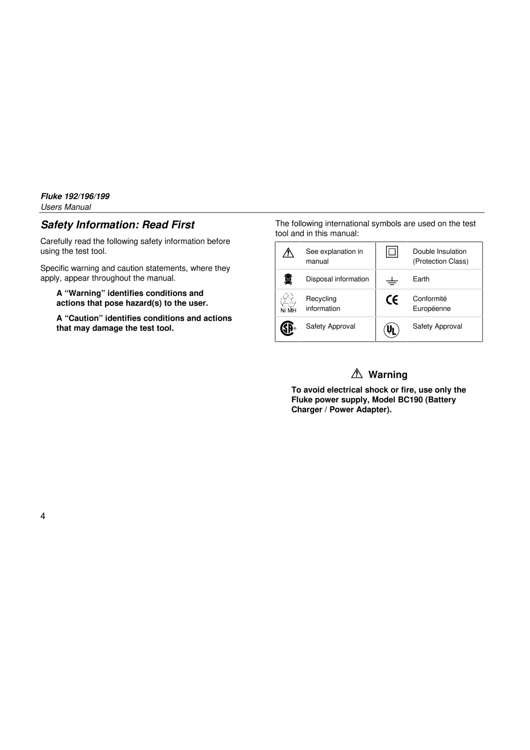
Safety Information Read First
Safety Information Read First
If Safety Features are Impaired
Use of the test tool in a manner not specified may
Impair the protection provided by the equipment
Using The Scope
Powering the Test Tool
About this Chapter
Resetting the Test Tool
Screen After Reset
Navigating a Menu
Open the Waveform Options
Hiding Key Labels and Menus
Input Connections
Making Scope Connections
Scope Connections
Displaying an Unknown Signal with Connect-and-View
Screen After an Auto Set
Making Automatic Scope Measurements
Select the Peak-Peak
Measurement
Freezing the Screen
Hz and V peak-peak as Scope Readings
Using Average, Persistence and Glitch Capture
Using Average for Smoothing Waveforms
Jump to Waveform
Using Persistence to Display Waveforms
Jump to Waveform and Select
Persistence , then select Infinite
Displaying Glitches
Suppressing High Frequency Noise
Acquiring Waveforms
Selecting AC-Coupling
Reversing the Polarity of the Displayed Waveform
Select 10kHz HF reject to
Analyzing Waveforms
Mathematics... to open
Mathematics menu
Or a vs B
Using The Multimeter
Making Meter Connections
Making Multimeter Measurements
Measuring Resistance Values
Making a Current Measurement
Highlight a ac
Open the Current Probe
Submenu
Ampere Measurement Readings
Freezing the Readings
Selecting Auto/Manual Ranges
Making Relative Measurements
Making a Relative Measurement
Using The Recorder Functions
Opening the Recorder Main Menu
Plotting Measurements Over Time TrendPlot
Starting a TrendPlot Function
Highlight Trend Plot Scope
Displaying Recorded Data
TrendPlot Reading
Changing the Recorder Options
Turning Off the TrendPlot Display
Open the Recorder Options
Menu
Recording Scope Waveforms In Deep Memory Scope Record
Starting a Scope Record Function
Highlight Scope Record
Using ScopeRecord in Single Sweep Mode
Using Scope Record in Triggered Single Sweep Mode
Jump to Display Glitches Select Yes, then jump to Mode
Level
Analyzing a TrendPlot or Scope Record
Triggered Single Sweep Recording
Using Replay, Zoom and Cursors
Replaying the 100 Most Recent Scope Screens
Replaying Step-by-Step
Replaying a Waveform
Replaying Continuously
Turning Off the Replay Function
Capturing 100 Intermittents Automatically
Zooming in on a Waveform
Zooming in a Waveform
Displaying the Zoomed Waveform
Turning Off the Zoom Function
Using Horizontal Cursors on a Waveform
Making Cursor Measurements
Using Vertical Cursors on a Waveform
Turn off the cursors
Using Cursors on a A+B, A-B or A*B Waveform
Making Rise Time Measurements
Triggering on Waveforms
Setting Trigger Level and Slope
Screen with all Trigger Information
Using Trigger Delay or Pre-trigger
Trigger Delay or Pre-trigger View
Automatic Trigger Options
Open the Trigger Options menu
Open the Automatic Trigger
Triggering on Edges
Open the Trigger Options menu Open the Trigger on Edge menu
Select Free Run, jump to Noise
Reject Filter
Triggering on Noisy Waveforms
Making a Single Acquisition
Select On Trigger, jump to Noise
Set Noise reject Filter to On
Making a Single Shot Measurement
Triggering on External Waveforms
Select 1.2V under the Ext Level
Label
Triggering on Video Signals
Enable video line selection
Triggering on Video Frames
Triggering on Video Lines
Triggering on Pulses
Detecting Narrow Pulses
Select On Trigger
Triggering on Narrow Glitches
Finding Missing Pulses
Open the Trigger Options menu Select On Trigger
Triggering on Missing Pulses
Using Memory, PC and Printer
Saving and Recalling
Saving Screens with Associated Setups
Deleting Screens with Associated Setups
Recalling Screens with Associated Setups
Display the SAVE/PRINT key labels
Recalling a Setup Configuration Viewing Stored Screens
Scroll through all stored screens
Connecting to a Computer
Documenting Screens
Connecting to a Printer
Connecting a Serial Printer
Setting up the Printing Configuration
Open the Printer Setup submenu
Printing a Screen
Baud Rate
Fluke 192/196/199
Using the Standard Accessories
Tips
Probing Using 2-mm Heavy Duty Test Probes
Heavy Duty Fixed Connections for Scope
Tips Using the Standard Accessories
Using the Independently Floating Isolated Inputs
Measuring Using Independently Floating Isolated Inputs
Tips Using the Independently Floating Isolated Inputs
Using the Tilt Stand
Suppressing Key Labels and Menu’s
Turn the test tool off
Press and hold
Adjusting the Contrast and Brightness
Changing the Information Language
Open the Language Select
Accept French as the language
Open Date Adjust menu
Changing Date and Time
Choose 1999, jump to Month
Choose 04, jump to Day
Saving Battery Life
Setting the Power Down Timer
Open the User Options menu Open the Auto Set Adjust Menu
Changing the Auto Set Options
To Coupling
Select Unchanged
Cleaning the Test Tool
Maintaining the Test Tool
Storing the Test Tool
Charging the Batteries
Charging the Batteries
Extending Battery Operation Time
Open the User Options menu
Replacing the NiMH Battery Pack BP190
Calibrating the Voltage Probes
Select 101, then return
Select Voltage, then jump to
Maintaining the Test Tool
Parts and Accessories
Standard Accessories
Displaying Calibration Information
Open the Version & Calibration
Standard Accessories
Ordering Code
TL24 General Purpose Leads
RS200
Optional Accessories
Troubleshooting
Battery Operated Fluke Accessories Do Not Function
FlukeView Does Not Recognize The Test Tool
Specifications
Performance Characteristics
Safety Characteristics
Introduction
Dual Input Oscilloscope
Isolated Inputs a and B Vertical
Horizontal
Trigger and Delay
Automatic Connect-and-View Trigger
Edge Trigger
Isolated External Trigger
Automatic Scope Measurements
AC Voltage VAC
AC+DC Voltage True RMS
Amperes AMP
Peak
Frequency Hz
Duty Cycle Duty
Power
Phase
Temperature Temp
Decibel dB
Meter
DMM Measurements on Meter Inputs
With Optional Temperature Probe
Diode
Recorder
TrendPlot Meter or Scope
Scope Record
Zoom, Replay and Cursors
Miscellaneous
Probe Calibration
Memory
Optical InterfacePort
Mechanical
Environmental
Safety
Max. Input Voltages
Max. Floating Voltage
Safety
Electrical specifications
Probe
Environmental
102
Electromagnetic Immunity
Disturbance less than 10% of full scale = 3V/m
104
Index
Numerics
106
107
108