Fluke Network Tester user manual Understanding the LEDs, Link/Collision/Error LED, Utilization LED

Models: Network Tester

1 102
Download 102 pages 54.69 Kb
Page 18
Image 18

NetTool

Users Manual

Understanding the LEDs

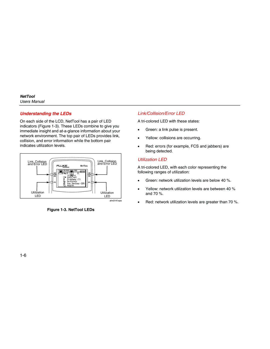
On each side of the LCD, NetTool has a pair of LED indicators (Figure 1-3). These LEDs combine to give you immediate insight and at-a-glance information about your network environment. The top pair of LEDs provides link, collision, and error information while the bottom pair indicates utilization levels.

Link, Collision

Link, Collision

and Error LED

and Error LED

Utilization

Utilization

LED

LED

ahn314f.eps

Figure 1-3. NetTool LEDs

Link/Collision/Error LED

A tri-colored LED with these states:

Green: a link pulse is present.

Yellow: collisions are occurring.

Red: errors (for example, FCS and jabbers) are being detected.

Utilization LED

A tri-colored LED, with each color representing the following ranges of utilization:

Green: network utilization levels are below 40 %.

Yellow: network utilization levels are between 40 % and 70 %.

Red: network utilization levels are greater than 70 %.

1-6

Page 18
Image 18
Fluke Network Tester user manual Understanding the LEDs, Link/Collision/Error LED, Utilization LED