DVD Location Recorder Model PD-6
8288 498
Page
Important notice
For a brand-new disk For a used disk
Page
Safety Instructions
Table of contents
Basic connections
Recording / playback
TC Setup mode
Setup mode
135
105
123
141
Precautions on safety
Precautions on installation
Manual organization
Setup mode
Utility mode
Main specifications
EDL SEL mode
Exporting files using IEEE1394
Rules of manual description
PD-6DVD Location Recorder
Introduction
Introduction
PD-6DVD Location Recorder Introduction
Options
Related products
PD-6 Carrying belt Centimeter DVD-RAM disk 2.8 GB
Before using the PD-6
Table of contents
Charging the battery
About power supply
About battery
Installing the battery
Removing the battery
Saving the battery power
Connecting the AC adaptor
About AC adaptor
Turning on the power
About power supply voltage
About Realtime Clock
About DVD-RAM disk
Side a
Inserting / removing a disk
Select Reel No using the SEL dial and press the Enter key
Initial format of a disk
Press the Exit key to exit the Utility mode
Format disk side B with the same procedure as above
Press the Enter key
One file mode
Two file mode
About recording modes
Right side panel section Top panel section
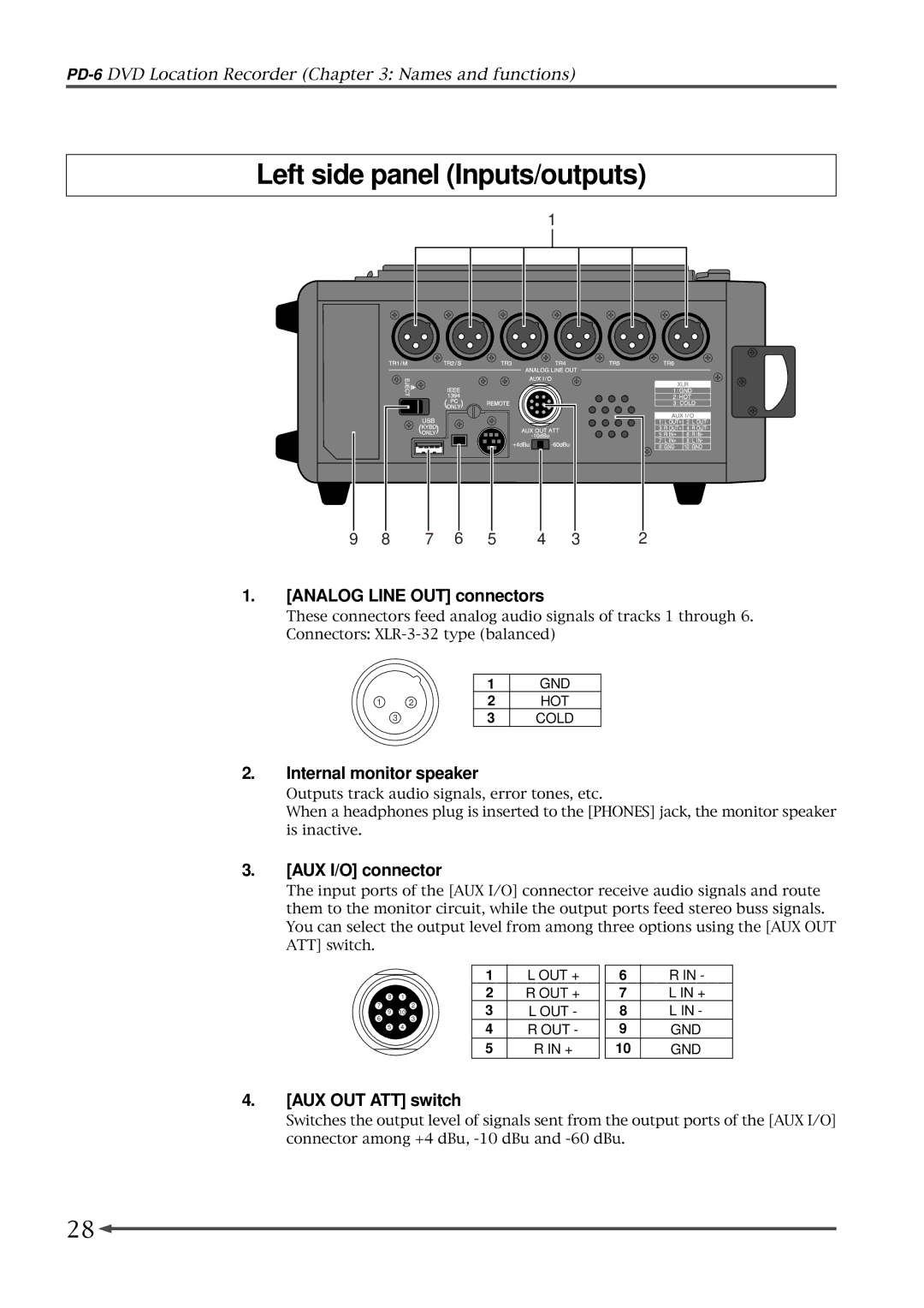
Left side panel section
AUX OUT ATT switch
Analog Line OUT connectors
AUX I/O connector
Left side panel Inputs/outputs
USB connector
Remote connector
IEEE1394 connector
Battery compartment
Power SEL INT/EXT switch
Analog MIC/LINE Input connectors
DC in 12V connector
DC OUT connectors
Word in terminate switch
Time Code OUT connector
Time Code in connector
Blank cap for installing the option
CONTRAST/TC Setup key
Power switch
Shift key/indicator
Front panel part
File SEL/EDL SEL key
SETUP/UTILITY key
TIME/DISP Mode key
Light key
Monitor mode select switch
Access indicator
Solo monitor select switch
16. ST/MONO monitor select switch
Clear key
Alphanumeric keys
Locate key
SKIP/CURSOR keys
Slate switch
Standby key/indicator green
REC key/indicator red
Circle Take key
Disc Feed switches
JAM switch
PRE REC switch
Peak indicators
Top panel part
PAN switches
TC GEN switch
Level controls
FS/24 switch
Frame switch
Clock switch
REC TR select switch
Pull UP/DOWN switch
Audio File select switch
TC OUT switch
Open lever
Input Mode switches
Phase switches
Input Gain controls
Stop key/indicator green
HPF switch
Limiter switch
Play key/indicator green
When no disk is set
LCD display
Initial screen Normal screen
Time display mode selection
When you set an unused disk
When you set a disk with recorded data
Display mode selection
TC Setup mode screen
Setup mode screen
Utility mode screen
Level meter section
CUE List screen
EDL SEL mode screen
Contrast adjust screen
File Select screen
Table of contents
Basic connections
Input connection
Analog audio input connection
Digital audio input connection
Sync signal connection
Monitor signal input connection
Time code input connection
Output connection
Analog audio output connection
Word clock output connection
Digital audio output connection
Time code output connection
Monitor output connection
Connection examples
Connection example for recording
For the backup purpose
Other connection examples
Example of PC connection
Example of USB keyboard connection
Function key
Power supply for external devices
Enters the TC Setup mode
Shortcuts
PD-6DVD Location Recorder Basic connections
Selecting the TC frame rate
Recording analog audio
Selecting an input source
Line input Mic input
Adjusting the input gain
Filter setting
Limiter setting
Selecting the sampling frequency
Selecting recording tracks
Adjusting the recording level
Selecting a recording source
ST/MONO monitor select switch
Monitoring recording signals
Monitor mode select switch
Solo monitor select switch
Making recording
To start recording, slide the REC key
To stop recording, press the Standby key
Recording with the PRE REC mode active
About overloading
Recording a slate tone/slate mic signal
Setting of the Disc Feed switch
PRE position BUS position Post position
File names of created audio files
Example B15h 11m 25s 07jan 2003.wav
Recording digital audio
Selecting digital input channels
Selecting the system master clock
TC OUT select switch
Recording time code
Selecting the TC frame rate
Selecting the TC generate mode
Setting the time code output
Page
Creating cue points
Creating a cue point on-the-fly
Viewing the cue point list
Editing a cue point
Editing a label
Creating a new cue point using the cue list screen
Editing time data
Deleting a cue point
Playback
Normal audio playback
Playback of a file recorded in two-file mode
Time code playback
Cueing playback
Skip/locate functions
Locating to the desired time
Locating to the desired cue point
PD-6DVD Location Recorder Recording/playback
TC Setup mode
How to select the TC Setup menu
Editing the LTC start time
Select the Edit LTC start menu and press the Enter key
Off
Time code output while paused
Select the Pause TC *** menu and press the Enter key
Or paused, no time code is output
User bit setting of playback time code
Select the TC Ubit ******** menu and press the Enter key
Editing the internal time code generator setting
Select the Set Gen. TC menu and press the Enter key
Select the JAM mode **** menu and press the Enter key
User bit setting of internal generator time code
Jam mode setting
Select the Gen Ubit ****** menu and press the Enter key
Setup mode
Setup menu details
Setup menu Parameter/options Default
How to select a Setup menu
Select the desired Setup menu using the SEL dial
Select the Adjust RTC menu and press the Enter key
How to make Setup menu setting
Adjusting the real-time clock Adjust RTC
Press the Exit key to exit the Setup mode
Select the Digital out ****** menu and press the Enter key
Setting the digital out format Digital out
Digital input channel setting Digital
AES/EBU
Skip mode setting Skip mode
Diagnoses on/off setting Diagnoses
Option Comment
Sets the input reference level to -20 dB default setting
Reference level setting Reference level
Peak hold time setting Peak hold
18dB Sets the input reference level to -18 dB
Slate tone recording time and mode setting Tone rec mode
Slate tone recording mode
Slate tone recording time Tone rec time
Auto cue mode on/off setting Auto cue
Pause cancel time setting Pause time
Infinity
Available conditions for generating the error tone
Error tone output setting Error tone
Write error
Input clip
Option Comment Off default Monitor speaker is not muted
Battery warning setting Batt warning
Speaker mute on/off setting Speaker mute
Disk warning
Threshold
Limiter parameter setting Limiter parameter
Grouping
Ratio compression ratio
Default file name setting Default file name
File name mode
100
Default track name setting Default track name
Next event number setting Next event No
Up to 16 Ascii characters can be entered as a track name
101
USB keyboard type setting Keyboard
Pre-record time setting Pre rec time
Options Comment US keyboard can be connected
102
Setup data saving Save user setup
Setup data loading Load user setup
User box selection
103
ROM version checking Version
104
105
106
Setting menu Function Default setting
Utility menu details
Execution menu Function
How to select a Utility menu
Select the desired Utility menu using the SEL dial
107
Select the Edit file name menu and press the Enter key
108
Editing a file name Edit file name
Enter the desired name
Checking file information
109
Editing a file information editing File info
Checking a description information
Line No Display Details of setting/execution
110
Adding a description information
111
Editing a description information
Deleting a description information
Select the Delete file menu and press the Enter key
Deleting an unnecessary audio file Delete file
112
Press the Enter again
Restoring a deleted audio file Restore Del. file
Select the Restore Del. file menu and press the Enter key
113
Optimizing the current disk Optimize disk
114
Select the Optimize disk menu and press the Enter key
115
How to enter a reel number volume label
Formatting the current disk Format
Select the Format menu and press the Enter key
Select the format mode, and press the Enter key
When selecting Normal When selecting Tape
116
Normal Tape
117
Editing the reel number volume label Reel No
118
Select the Reel No **** menu and press the Enter key
Selecting the record protection on or off Rec protect
119
Select the Rec protect *** menu and press the Enter key
Selecting the resume function on or off Resume
120
Select the Resume *** menu and press the Enter key
Setting IEEE1394 connection IEEE1394
121
Select the IEEE1394 **** menu and press the Enter key
122
127
123
124
129
About an ALE file
Creating a new ALE file
124
While New file is flashing, press the Enter key
Sets the reel number Tape of an ALE file
125
Menu Function
TC frame
While Video format is highlighted, press the Enter key
After making necessary settings, press the Exit key
126
Menu Options
Adding audio files to an ALE file
127
While ALL-TAKE.ale is highlighted, press the Enter key
While New entry is highlighted, press the Enter key
Press the Exit key to exit the EDL SEL mode
128
After adding audio file entries, press the Exit key
Viewing and editing audio file entries
129
Viewing audio file entries
Deleting an audio file entry
130
Adding an audio file entry to an existing ALE file
Press the Exit key twice
Editing an ALE file name
Editing an ALE file
131
After completing editing the name, press the Enter key
132
Remaking an ALE file
133
Deleting an ALE file
134
135
137
138
136
Windows Windows 98SE, ME Read is only possible
How to disconnect the PD-6
Connection between the PD-6 and a PC
137
Example of copying data to an external hard disk
Example of exporting data to a computer application
138
139
Click Convert -, followed by Done indicated by arrow
140
Specifications
141
Time Code Input
142
Line
Time Code Output
143
144
Declaration of EC Directive
Affect of Immunity on This Equipment
145
Page
Page
35, Musashino, Akishima-shi, Tokyo, Japan
15431, Blackburn Ave., Norwalk, CA 90650, U. S. a