VM200
Safety Instructions
VM200
Getting Started
Monitoring Signals
Scene Memory
Initializing the VM200
VM200 User’s Guide
VM200
About This Chapter
Using this Guide
Welcome to the VM200
Installing the VM200
Feature Summary
Audio Specifications
Inputs and Outputs
Mixer Functions
Midi functions
Why a Digital Mixer?
Mixer Configuration
Digital I/O
Four-band Parametric EQ & EQ Library
Dual On-board Effects Processors
About the Display and Graphic User Interface
Faders
Scene Memory
Touring
Top Panel Control Surface
VM200
Analog Control Section
PAD 26dB switches
2TRK in switch
Input selectors
LCD Display
Data Wheel and Neighboring Keys
+1/ Keys
Enter and Exit Keys
Function Keys
Setup Section
System Key
Midi Key
Key Mode Section
ROUTING/PHASE Key
Current Scene Status
PAIR/GROUP Key
CH View Key
CHANNEL/METER Key
EFF1 and EFF2 Keys
Fader Mode Section
AUX1, AUX2, AUX3, and AUX4 Keys
Channel Key
Recall Key
EQ Library
EQ on Key
Store Key
Eff Edit Section
Effect Library
Rec Buss Section
Scene Memory Section
Solo Key
Channel Control Section
Fader function
ON, SOLO, & EQ Edit Keys
On Keys
On key function
Solo Keys
Solo key function
EQ Edit Keys
EQ Section Rotary Controls
EQ Edit key function
Select Keys
Rear Panel
2TRK
Inputs 5 8 Phone Connectors
Inputs 1 4 XLR or Phone Connectors a or B
+48 Phantom Power
Inserts 1-4 Phone Connectors
Power Switch
75Ω On, Off Switch
Diagram
Block
VM200 User’s Guide
Started
VM200 System Example
Phones
Connecting the Power Cord
Turning the VM200 On and Off
Few Tips on Using the VM200
Channel Layers
Analog
Keeping It Digital
An Important Note About Word Clock Information
Stopless Rotary Controls
Lower and Raise Faders to Initiate Sends
Reading the Display
Channel Edit Function
Examples of Other Function Pages
Function Page Parameter Matrix
Lit & Flashing LED Keys
Lit & Flashing LED Keys
Finally...Let’s Get Started
Making Connections
Connect the ST Buss OUT to the analog inputs of a recorder
Powering On
Adjusting the Channel Input
Lower all faders and Gain and Trim knobs on the VM200
Adjusting the EQ
Press the channel 1 EQ Edit key
Adjusting the EQ
Audition Some Effects
Press the EFF2 key in the Eff Edit section
Press the Recall key in the Eff Library section
Storing a Mix Scene
Press the EFF2 key in the Fader Mode section
Recording
Press the 17-20 EFF RTN Page Select key
VM200 User’s Guide
Channels
Input Channels
Phantom Power for Input Channels
Insert Channels
Pad Switches Input channels
Trim Controls
Inverting the Input Phase
Press the Exit key or the CHANNEL/METER key
Muting Channels
Setting Channel Levels
Input Channel EQ
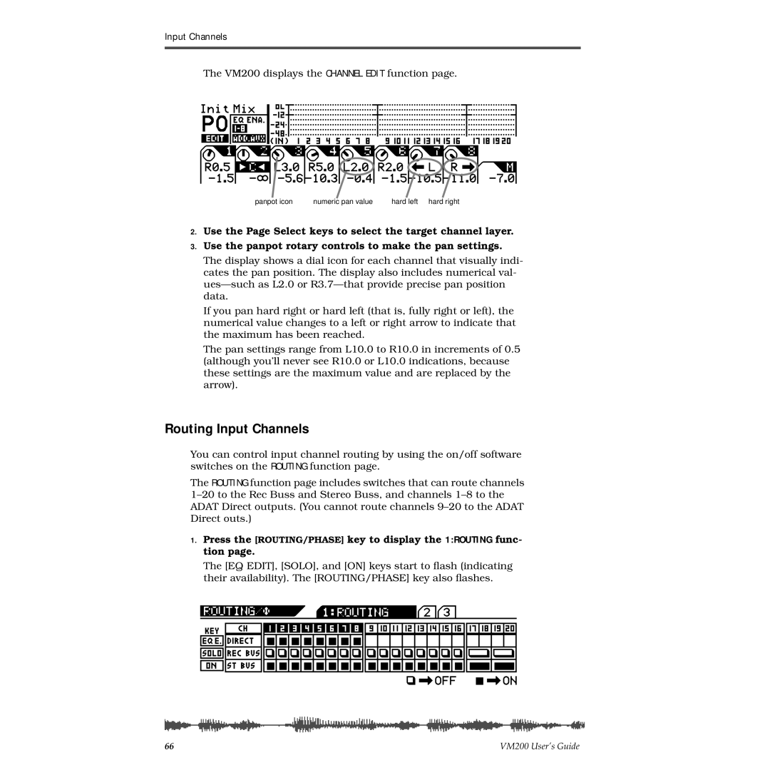
Panning Input Channels
Routing Input Channels
REC Buss Out
Monitoring and Soloing Input Channels
Feeding Outputs
ST Buss Out
Digital Outs
Pairing Channels
Grouping Mute Channels
Press the PAIR/GROUP key to display the 1CH Pair function
Grouping Faders
Viewing Input Channel Settings
Press the CH View key to display the 1CH View function
Press the EQ Edit key for the target channel
Copying Channel Settings
Press the Enter key to execute the copy operation
VM200 User’s Guide
Chapter Contents
Equalizers EQ
Adjusting the EQ
Press the EQ on key in the Selected EQ section to turn it on
Lo-Mid Hi-Mid Gain G
Press the Enter key to confirm your selection
EQ Enabling Channels
Bypassing the EQ
Press the EQ on key in the Selected EQ section
Resetting the EQ
While pressing and holding down the Enter key, press
VM200 User’s Guide
EQ Preset Library List
Name
Recalling EQ Programs
Press the Enter key to recall the desired EQ Program
Recalling EQ Programs
Storing EQ Programs
Press the Enter key
Storing EQ Programs
Editing EQ Program Titles
EQ Library Name Edit function pages
Copying EQ Settings
Copying EQ Settings
EQ Preset Library Parameters
Name Parameter Description Lo-Mid Hi-Mid Gain
Distortion of popular
Description Lo-Mid Hi-Mid Gain
VM200 User’s Guide
Monitoring Signals
Solo Mode Parameter
Monitoring and Soloing
MON SEL Parameter
Monitor Outs and Phones
Two Track Input 2TRK
Press the Setup System key
Monitoring
Soloing
Solo KEY Parameter Options Latch
Selected Solo keys light up
Press the Setup System key four times from start of cycle
Solo Safe Function
Metering Signal Levels
Viewing Input/Output Level Meters
Press the CHANNEL/METER key or the Exit key in most modes
LED Display Meter L/R or ST BUSS/SOLO
Press the CH View key
Chapter Contents
Outputs
Overview
Adat OUT & S/P DIF OUT
Using the ST Buss OUT
Monitoring the ST Buss OUT
Viewing the ST Buss OUT Meters
Setting the ST Buss OUT Level
Soloing the ST Buss OUT
Muting the ST Buss OUT
Using the REC Buss OUT
Monitoring the REC Buss OUT
Viewing the REC Buss OUT Meters
Setting the REC Buss OUT Level
Soloing the REC Buss OUT
114 VM200 UserÕs Guide
Using the AUX Sends
Enabling AUX Sends 3 & 4 ADD. AUX Parameter
Viewing the AUX Send and Master Setting
Monitoring AUX Sends
Sending Channel Signals to AUX Sends
Pre-fader/Post-fader AUX Sends
Muting AUX Sends
Use the Master on button to turn the AUX Send on and off
Pairing AUX Sends
Press the Exit key to return to Channel Edit mode
Press the Enter key to confirm the setting
Smoothing Function
Viewing Buss Routing for Each Channel
122
Effects
VM200 Effects
Effect Preset Library List
Effects Library
Reverb effects
Delays
Early Reflection-type Reverbs
Modulation effects
Pitch Changer
Multi-effects
Selecting an Effects Processor
Setting Effects Return
Applying Effects
Press the CHANNEL/METER key
Sending Signal to Effects Processor
Routing Effects Returns
Controlling the Sends Signals
Viewing and Adjusting the Effect Send Level
Pre-fader/Post-fader Effect Sends
Viewing and Adjusting the Effect Send Master Level
Raise the fader for the corresponding channel
Muting Effect Sends
Controlling the Return Signals
Setting the Effect Return Level
Monitoring Effects Sends
Editing Effects
Recalling Effects Programs
Storing Effects Programs
Press the Store key in the Eff Library section
EFF Library Name Edit function pages
Editing Effect Program Titles
Press the Enter key to recall the desired Effect program
138
Effects Parameters
Reverb-type Effects
Early Reflection-type Effects
Monodelay
Dualdelay
3CHDELAY
Chorus
3DCHORUS
Monopitch
Delay-Reverb-type Effects
CHORUS-REVERB
REVERB-CHORUS
REVERB-FLANGE
Memory
What is Scene Memory?
Scene Edit Indicator
What Can You Store in a Scene?
Preset Scene Memory
AUX
Recalling Mix Scenes
Recalling a Scene Manually
Recalling a Scene Automatically at Start-up
Recalling Mix Scenes Using Midi Program Change Messages
Press the System key five times
Assign Program Change messages to scene memories
Motorized Faders
Storing Mix Scenes
Press the Scene Memory Store key
When you’ve finished naming the scene, press the Enter key
Specifying Recall Safe Channels
Editing Scene Memory Titles
Recall Safe Function
Press the System key three times
Press the CHANNEL/METER key to return to Channel Edit mode
Specifying Recall Safe Parameters
158
Connections
Digital Connections, Word Clocks, and Sample Rates
161
Setting the Master Word Clock
Word Clock Setup
Word IN/OUT Connectors
Press the System key
Setting the VM200 as Master or Slave
Recording to a Digital Multitrack Recorder or DAT
Multitrack Recording and Mastering to a DAT
VM200 is word clock Slave
Using Adat
Digital I/Os
Using Adat OUT
Assigning Channels to Adat Direct SENDs
167
Using S/P DIF OUT
Using S/P DIF
Assigning S/P DIF Signals to Channels
Press the ROUTING/PHASE key twice
Press the CHANNEL/METER key or Exit key
Cascading the VM200
172
VM200
Using the VM200 with Midi
Midi Ports
Connecting Midi devices
Cascading Two VM200s
Midi Transmit and Receive Channels
TX CH Transmit Channel
RX CH Receive Channel
Program Change RX
Program Change Messages
Program Change TX
Program Change Table
Control Change RX
Control Change Messages
Control Change TX
Control Change Table
System Exclusive TX & RX
System Exclusive Messages Fostex Exclusive
Bulk Dump
System Exclusive DevID
Using Program Change Messages to Recall Scenes
Press the Midi key
Set the TX CH and/or RX CH parameters to on
Select a Program Change number
Editing the User Program Change Assign Table
Press the Midi key twice
Select a Scene number
Viewing the Preset Program Change Assign Table
Press the Midi key three times
Program Change Assign Table Notes
Examples Using Program Change Messages
Using Control Change Messages
Editing the Control Change Assign Table
Press the Midi key four times
Select a Control Change number
Viewing the Preset Control Change Assign Table
Press the Midi key five times
Control Change Assign Table Notes
Examples Using Control Change Messages
Controlling Parameters Using Fostex Exclusive Messages
Bulk Dump
Transmitting Midi Bulk Dump Messages
Automatic transmission in response to Bulk Dump Request
Manual transmission of Bulk Dump Messages
Specifying the data you want to transfer
Receiving Bulk Dump Requests
Receiving Bulk Dump Requests
MMC Midi Machine Control Send
Setting the Device ID Number
Entering MMC Send Mode
Select an ID number for the DevID parameter
193
Frame Mode
MMC Send and Timecode
Press the CHANNEL/METER key or the Exit key
Transmitting the Locate Commands
Storing Locate Points
Checking the Locate Points
196
Initializing the VM200
Initializing the VM200
199
Default Setup Parameters
System Parameters Value
Data
Chapter C ontents
EQ 1-8 Invalid! EQ Enable
Display Warning Messages
Specifications
Inputs
Outputs
General
Midi IN/OUT/THRU
Maintenance
Maintenance
Tables & Data
Channel Fader Gain Table
Master Fader Gain
Pan Gain
Left Right Pan
EQ Frequency
Range 20.3Hz 20.2kHz 240 steps per 1/24 octave
Program Change AssignTable 2 Preset
Program Change To Scene Memory Assignment Tables
Program Change Assign User
Control Change To Control Parameters Assignment Tables
Control Change Assign User
Control Change Assign Preset
Preset Scene Parameters
P0 InitMix
P1 Recording
P2 MixDown
Motion Control Process MCP MMC Locate target
Midi In/Out Data Format
Control Change Bn
Program Change Bn
Command List
Fostex Exclusive Message
Remote Command
Command Details
Setup Commands
Channel/Buss Commands
221
Effects Commands
Bulk Dump & Request
Bulk Dump Request
Midi Device Inquiry Message
Midi Implementation Chart
Model VM200 Version1.0
Declaration of EC Directive
Affect of Immunity on This Equipment
Fostex Distributors List In Europe
227
228
Index
230 VM200 User’s Guide
VM200 User’s Guide 231
Symbols Numerics
Page
Fostex Corporation