7-3: REPLACE TRANSFORMER
1.Unplug all power cords. Perform Procedure
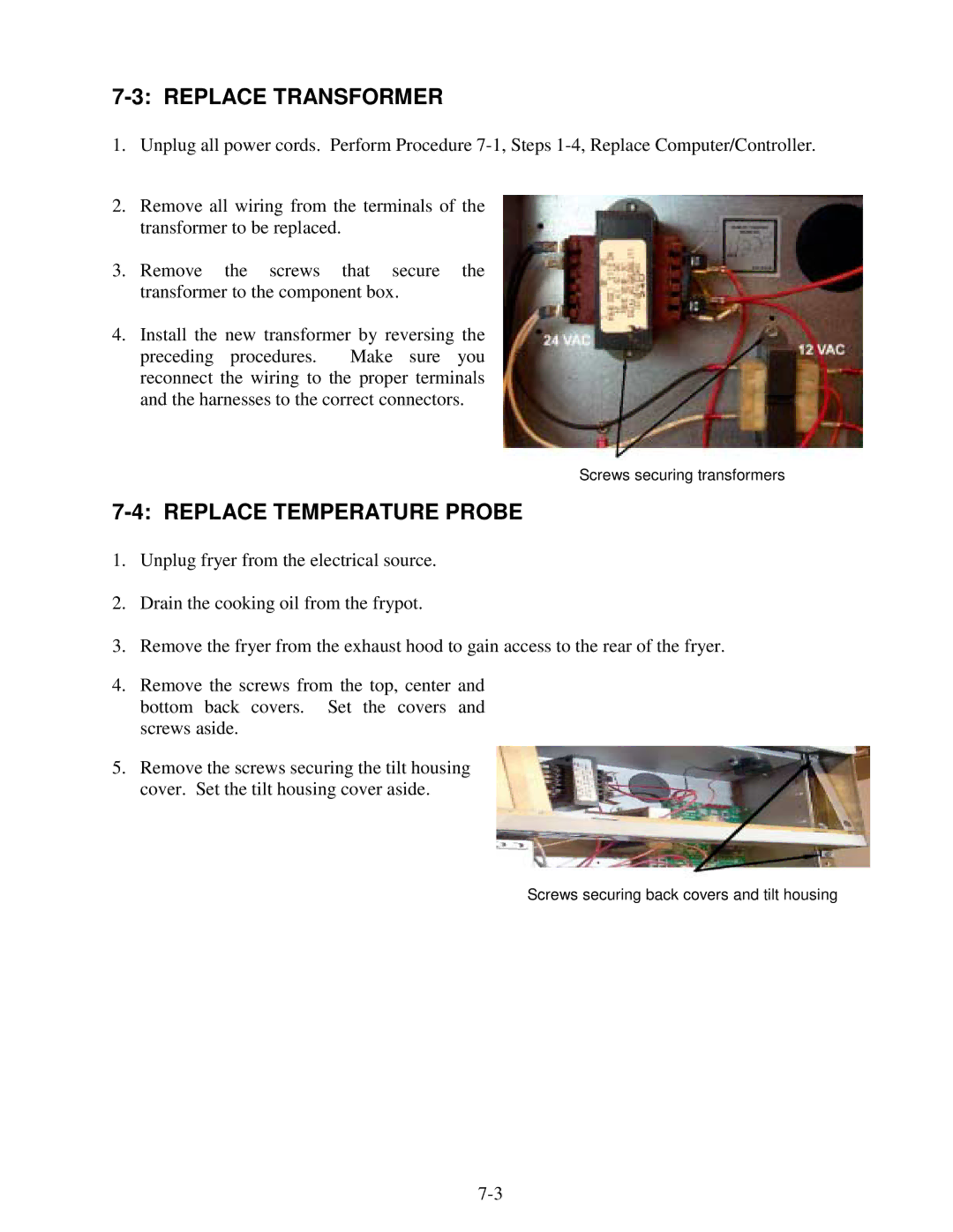
2.Remove all wiring from the terminals of the transformer to be replaced.
3.Remove the screws that secure the transformer to the component box.
4.Install the new transformer by reversing the preceding procedures. Make sure you reconnect the wiring to the proper terminals and the harnesses to the correct connectors.
Screws securing transformers
7-4: REPLACE TEMPERATURE PROBE
1.Unplug fryer from the electrical source.
2.Drain the cooking oil from the frypot.
3.Remove the fryer from the exhaust hood to gain access to the rear of the fryer.
4.Remove the screws from the top, center and bottom back covers. Set the covers and screws aside.
5.Remove the screws securing the tilt housing cover. Set the tilt housing cover aside.
Screws securing back covers and tilt housing