7-10: BUILT-IN FILTER SYSTEM SERVICE PROCEDURES (cont.)
If the motor runs but the pump does not, there is a blockage in the pump. Incorrectly sized or
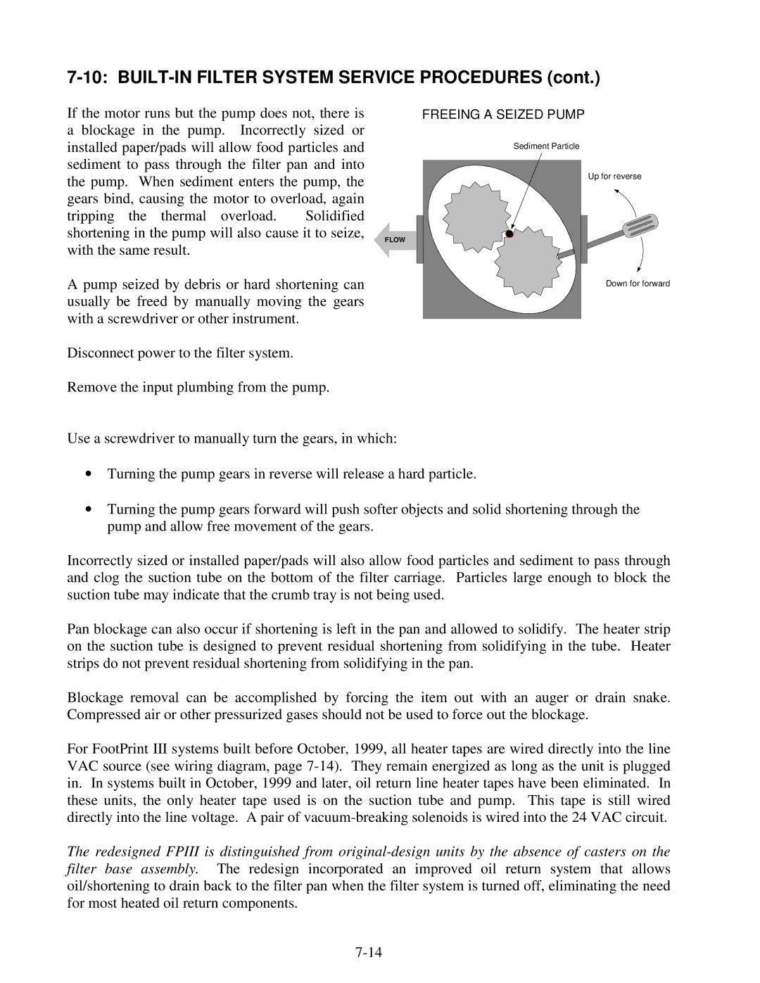
FREEING A SEIZED PUMP
installed paper/pads will allow food particles and sediment to pass through the filter pan and into the pump. When sediment enters the pump, the gears bind, causing the motor to overload, again tripping the thermal overload. Solidified shortening in the pump will also cause it to seize, with the same result.
A pump seized by debris or hard shortening can usually be freed by manually moving the gears with a screwdriver or other instrument.
Sediment Particle
FLOW |
Up for reverse
Down for forward
Disconnect power to the filter system.
Remove the input plumbing from the pump.
Use a screwdriver to manually turn the gears, in which:
•Turning the pump gears in reverse will release a hard particle.
•Turning the pump gears forward will push softer objects and solid shortening through the pump and allow free movement of the gears.
Incorrectly sized or installed paper/pads will also allow food particles and sediment to pass through and clog the suction tube on the bottom of the filter carriage. Particles large enough to block the suction tube may indicate that the crumb tray is not being used.
Pan blockage can also occur if shortening is left in the pan and allowed to solidify. The heater strip on the suction tube is designed to prevent residual shortening from solidifying in the tube. Heater strips do not prevent residual shortening from solidifying in the pan.
Blockage removal can be accomplished by forcing the item out with an auger or drain snake. Compressed air or other pressurized gases should not be used to force out the blockage.
For FootPrint III systems built before October, 1999, all heater tapes are wired directly into the line VAC source (see wiring diagram, page
The redesigned FPIII is distinguished from