Manuals
/
Frymaster
/
Kitchen Appliance
/
Fryer
Frymaster
H14 Series
service manual
McDonald’s European Community CE Prior To 9/98
Models:
H14 Series
1
73
110
110
Download
110 pages
58.94 Kb
70
71
72
73
74
75
76
77
Install
FootPrint III Wiring Diagram
Warranty
Filtration Problem Resolution
Diagnostic LED Legend
Accessories
1 M-100B Computer Setup Mode
Control Panel Assembly
Service Procedures
Recovery Out of Range REC LOC
Page 73
Image 73
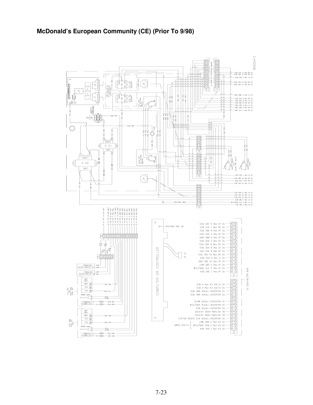
McDonald’s European Community (CE) (Prior To 9/98)
7-23
Page 72
Page 74
Page 73
Image 73
Page 72
Page 74
Contents
Frymaster H14 Series Electric Fryer
Computers FCC
Warranty Statement
Parts Return
Introduction
Safety Information
General
European Community CE Specific Information
Computer Information
Service Information
Shipping Damage Claim Procedure
Do not block the area around the base or under the fryers
Installation Instructions
After Fryers Are Under The Fry Station Hood
Power Requirements
Frypot Boil-Out
Operating Fryers With M100B Cooking Computers
Equipment Setup and Shutdown Procedures
Introduction To The M-100B Cooking Computer
Shutdown
Description
Operating the Computer on Full-Vat Fryers
M-100B Computer Operating Instructions
Operating the Computer on Split-Vat Fryers
Open Drain Valve Indication
M-100B Computer Problem Condition Indicators
Recovery Out of Range REC LOC
How to Enter the Setup Mode
1 M-100B Computer Setup Mode
M-100B Computer Set-Up and Programming Instructions
How to Configure the Computer for Use on an Electric Fryer
How to Change the Computer’s Display Language
How to Change Computer Product/Temperature Displays
How to Activate or Deactivate the Frypot BOIL-OUT Feature
How to Enter the Program Mode
2 M-100B Computer Programming Mode
How to Reset the Computer to the Factory Defaults
How to Enter a Product Name in a Test Menu
How to Change the Cooking Temperature Setpoint
Page
How to Suppress a Shake, QA, or Duty Function
How to Display the Product Cycle Accumulator Information
How to Display Use Time Information
How to Use the Filter Countdown Timer
Introduction to the Analog Controller
Operating Fryers With Analog Controllers
I J K L M N
Analog Controller High-Limit Check
Analog Controller Operating Instructions
Page
Description Function
Operating the BUILT-IN Filtration System
STEP-BY-STEP Filtration Instructions
Page
Page
Page
Page
Page
Page
Page
Care and Cleaning of Your Fryer and Filter System
Water in the Filter PAN
MSDU50
Preventive Maintenance Troubleshooting
Preventive Maintenance and Troubleshooting
Computer Panel Open Interface Board Visible
Computer Panel Open Interface Board Visible
Fryer Heating Oil
From Preceeding
From Preceeding
Is the AL LED illuminated?
Controller Panel Open Interface Board Visible
From Preceeding
From Preceeding
Filter System Operation
Pump Motor Actuation
Replace Controller
Service Procedures
Replace Interface Board
Replace Transformer
Replace Temperature Probe
Replace Temperature Probe
Replace Heating Element
Replace Heating Element
Remove the element mounting screws
Left element- 9-pin Right element- 6-pin Connector
Replace HIGH-LIMIT
Replace Frypot
Replace Contactor
Contactor mounting screws
Filtration Problem Resolution
BUILT-IN Filter System Service Procedures
BUILT-IN Filter System Service Procedures
FootPrint III Wiring Diagram
Diagnostic LED Legend
Electric Interface Board Diagnostic Chart
Common Electric McDONALDS H14 SERIES- FULL-VAT
Wiring Diagrams
Simplified
GND
Common Electric McDONALDS H14 SERIES- DUAL-VAT
Common Electric McDONALDS H14 SERIES- FULL-VAT- Export WYE
Common Electric McDONALDS H14 SERIES- DUAL-VAT- Export WYE
McDonald’s Domestic
Wiring DIAGRAMS, Main
McDonald’s European Community CE
McDonald’s European Community CE Prior To 9/98
McDonald’s European Community CE XBIH14
McDonald’s Domestic Contactor
McDonald’s European Community CE WYE Contactor
McDonald’s European Community CE XBIH14 Contactor
McDonald’s 440/480V Contactor
McDonald’s Delta CSA Contactor
McDonald’s Domestic Control Cord
McDonald’s English Control Cord
Footprint III, Early Configuration
Wiring DIAGRAMS, Filter Units
Footprint III, Late Configuration
Accessories
H14 Series Electric Fryers Parts List
Page
Side , Cabinet
2 MH/BIH214, 314, 414, 514 Cabinet Assemblies
Component
Casters, Legs and Associated Hardware
Component Box Assemblies/Associated Component Parts
Page
Control Panel Assembly
Door Assembly Components
Controller Assemblies
Drain System Components
Page
McDonald’s Domestic, Dual-vat
Elements and Related Components
Component
Hood Relay Box, Power Cords and Hood Cords
Filter Base/Pan Assemblies 8.9.1 Filter Base Assemblies
Filter Base Assembly, FootPrint
Filter Pan Assemblies
Filter Pan Assembly, Single FootPrint
Filter Pump and Motor Assemblies
Pump and Motor Assembly, 250V 50/60 Hz
Page
Flex Line Assembly, With Male/Female Ends
Oil Return Linkage Assemblies and Components
Frypot Assemblies and Drain Valve Components
Thermostats and Related Components
Top
Page
Image
Contents