Host Interface
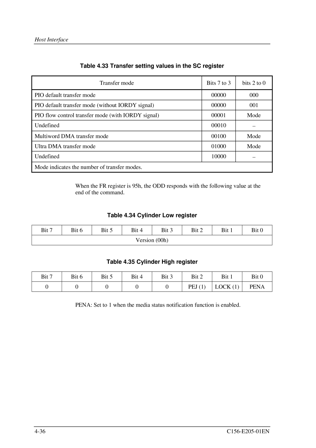
Table 4.33 Transfer setting values in the SC register
Transfer mode | Bits 7 to 3 | bits 2 to 0 |
|
|
|
PIO default transfer mode | 00000 | 000 |
|
|
|
PIO default transfer mode (without IORDY signal) | 00000 | 001 |
|
|
|
PIO flow control transfer mode (with IORDY signal) | 00001 | Mode |
|
|
|
Undefined | 00010 | ∀ |
|
|
|
Multiword DMA transfer mode | 00100 | Mode |
|
|
|
Ultra DMA transfer mode | 01000 | Mode |
|
|
|
Undefined | 10000 | ∀ |
|
|
|
Mode indicates the number of transfer modes. |
|
|
|
|
|
When the FR register is 95h, the ODD responds with the following value at the end of the command.
Table 4.34 Cylinder Low register
Bit 7
Bit 6
Bit 5
Bit 4
Bit 3
Bit 2
Bit 1
Bit 0
Version (00h)
Table 4.35 Cylinder High register
Bit | 7 | Bit | 6 | Bit | 5 | Bit | 4 | Bit | 3 | Bit 2 | Bit 1 | Bit 0 |
|
|
|
|
|
|
|
|
|
|
|
|
|
0 |
| 0 |
| 0 |
| 0 |
| 0 |
| PEJ (1) | LOCK (1) | PENA |
|
|
|
|
|
|
|
|
|
|
|
|
|
PENA: Set to 1 when the media status notification function is enabled.
