Host Interface
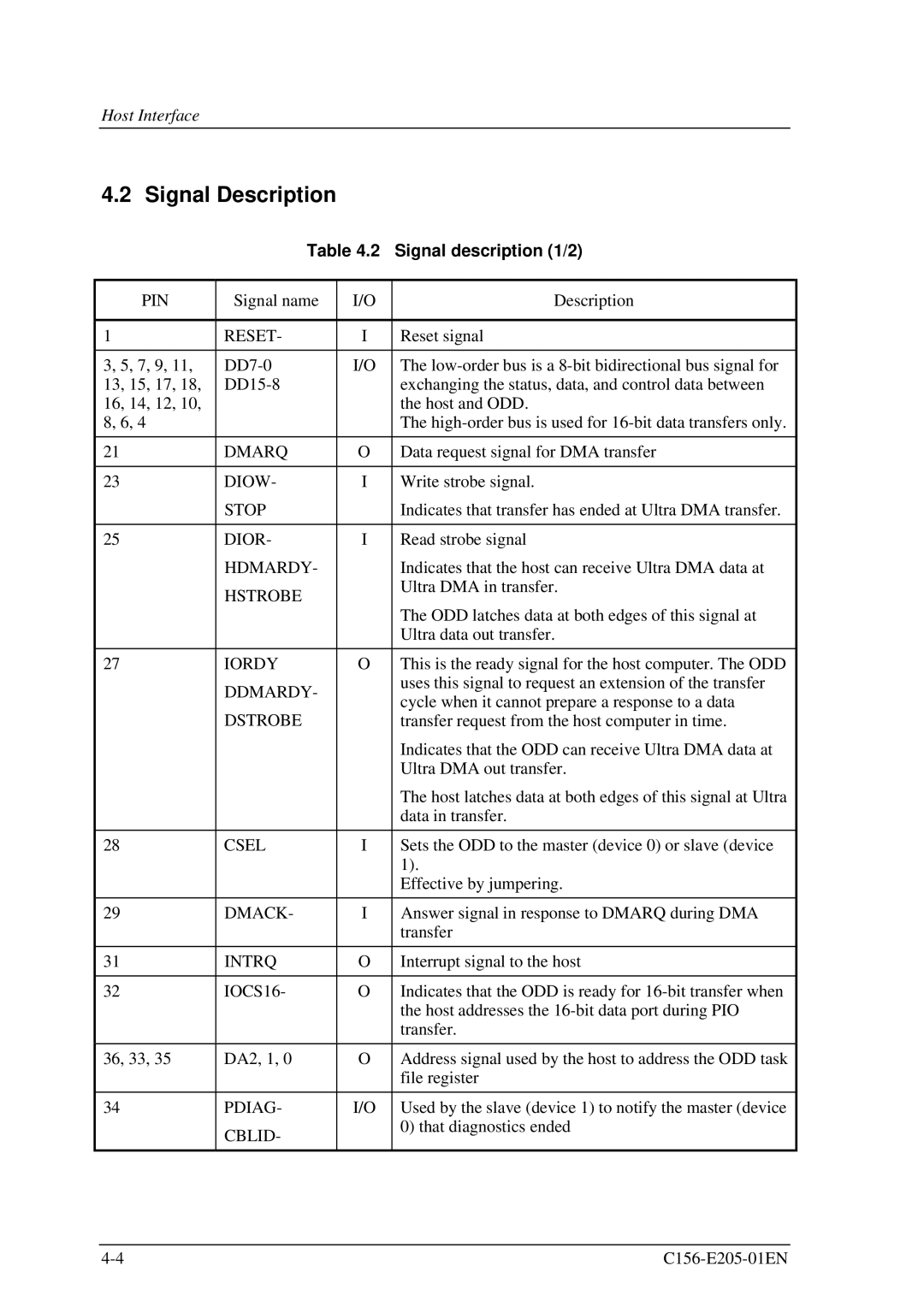
4.2 Signal Description
Table 4.2 Signal description (1/2)
PIN | Signal name | I/O | Description |
|
|
|
|
1 | RESET- | I | Reset signal |
|
|
|
|
3, 5, 7, 9, 11, | I/O | The | |
13, 15, 17, 18, |
| exchanging the status, data, and control data between | |
16, 14, 12, 10, |
|
| the host and ODD. |
8, 6, 4 |
|
| The |
|
|
|
|
21 | DMARQ | O | Data request signal for DMA transfer |
|
|
|
|
23 | DIOW- | I | Write strobe signal. |
| STOP |
| Indicates that transfer has ended at Ultra DMA transfer. |
|
|
|
|
25 | DIOR- | I | Read strobe signal |
| HDMARDY- |
| Indicates that the host can receive Ultra DMA data at |
| HSTROBE |
| Ultra DMA in transfer. |
|
|
| |
|
|
| The ODD latches data at both edges of this signal at |
|
|
| Ultra data out transfer. |
|
|
|
|
27 | IORDY | O | This is the ready signal for the host computer. The ODD |
| DDMARDY- |
| uses this signal to request an extension of the transfer |
|
| cycle when it cannot prepare a response to a data | |
| DSTROBE |
| |
|
| transfer request from the host computer in time. | |
|
|
| Indicates that the ODD can receive Ultra DMA data at |
|
|
| Ultra DMA out transfer. |
|
|
| The host latches data at both edges of this signal at Ultra |
|
|
| data in transfer. |
|
|
|
|
28 | CSEL | I | Sets the ODD to the master (device 0) or slave (device |
|
|
| 1). |
|
|
| Effective by jumpering. |
|
|
|
|
29 | DMACK- | I | Answer signal in response to DMARQ during DMA |
|
|
| transfer |
|
|
|
|
31 | INTRQ | O | Interrupt signal to the host |
|
|
|
|
32 | IOCS16- | O | Indicates that the ODD is ready for |
|
|
| the host addresses the |
|
|
| transfer. |
|
|
|
|
36, 33, 35 | DA2, 1, 0 | O | Address signal used by the host to address the ODD task |
|
|
| file register |
|
|
|
|
34 | PDIAG- | I/O | Used by the slave (device 1) to notify the master (device |
| CBLID- |
| 0) that diagnostics ended |
|
|
| |
|
|
|
|
