UNIT INSTALLATION continued
B.Install the nipple assembly into the elbow (3/4” NPT) Refer to Photo A
C.Install the manifold support bracket over the nipple attaching it to the circular bracket on the nipple. Do not tighten screws. Refer to Photo B
Photo B
D.Adjust the manifold support bracket flush with the rear gas support bracket. Refer to Photo B
E.Tighten the loose screws of the manifold support bracket. Refer to Photo B
F.Lock the two brackets together using two screws. Refer to Photo C
Photo C
Accessory Kit – Electrical Supply Lines:
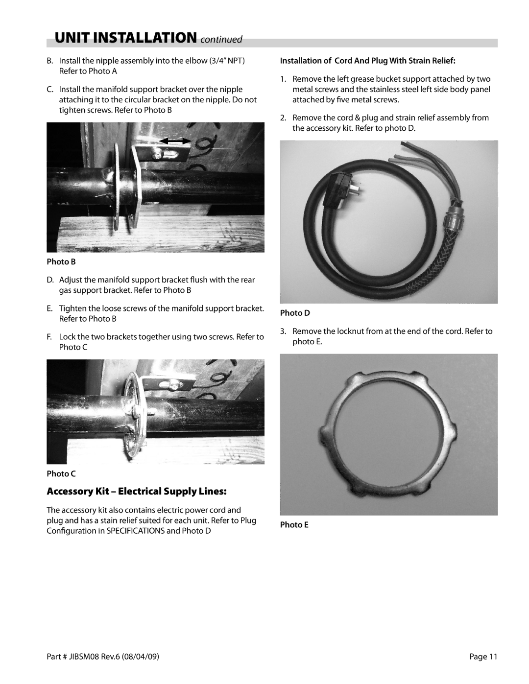
The accessory kit also contains electric power cord and plug and has a stain relief suited for each unit. Refer to Plug Configuration in SPECIFICATIONS and Photo D
Installation of Cord And Plug With Strain Relief:
1.Remove the left grease bucket support attached by two metal screws and the stainless steel left side body panel attached by five metal screws.
2.Remove the cord & plug and strain relief assembly from the accessory kit. Refer to photo D.
Photo D
3.Remove the locknut from at the end of the cord. Refer to photo E.
Photo E
Part # JIBSM08 Rev.6 (08/04/09) | Page 11 |