UNIT INSTALLATION continued
The gas valve, enrichment tube igniter and orifice must be changed to that supplied by the Authorized Service Agency for the gas you are changing to. On completion of changing these three components, you should test all joints for leaks, verify that the manifold pressure is adjusted to the value given in the specification pages in this manual, and repeat the burner air adjustment procedure. This is to be found on the following page in this manual. When the burner is correctly adjusted, the alternate rating plate decal must be placed over the existing rating plates to reflect the new category for which the grill is set.
To change from one gas type to another within the same category (High to Low Calorific Value Natural Gas or vice versa), change the orifice to that supplied by the Authorized Service Agency.
Burner Air Adjustment
1.The Xpress Grill gas model burner is a stainless steel rectangular assembly that receives forced air from a fan mounted below the burner. The fan air quality can be slightly adjusted if the flame quality is poor to the point that the flame sensor will be unreliable.
2.Loosen the lock nut holding the air adjustment in place. Slowly turn the air adjustment out (counterclockwise). The flame should be stable (no lifting) and be 1/8” to 1/4” predominately blue.
Igniter Adjustment
The Igniter location is factory set and does not normally require adjustment. Adjustment should only be conducted if the
Note: the correct air fuel mixture and gas pressures must be obtained before proceeding with igniter adjustment
1.Loosen the two 5\16” hex head #10 screws just outboard of the igniter. This allows the igniter and its bracket vertical movement.
2.With the Microamp meter in the flame sense line, and the adjustment screws just loose enough to be able to move the igniter assembly up and down, ignite the burner and move the igniter up and down until the maximum Microamp reading is achieved.
3.Tighten up the adjuster screws and the job is complete.
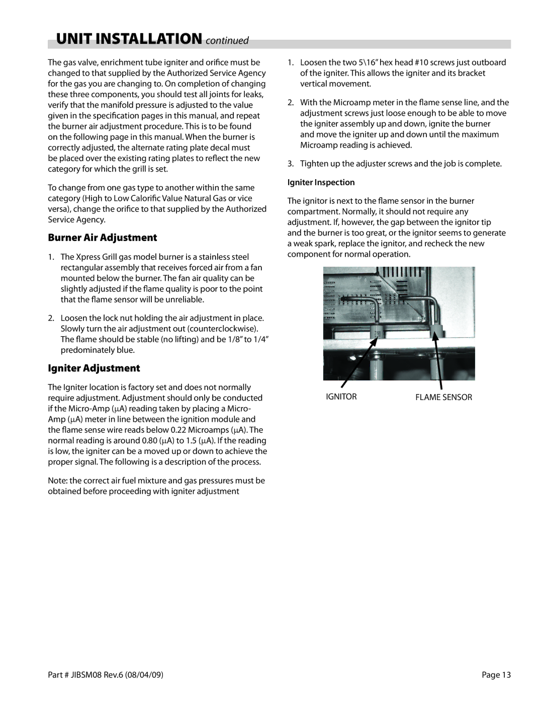
Igniter Inspection
The ignitor is next to the flame sensor in the burner compartment. Normally, it should not require any adjustment. If, however, the gap between the ignitor tip and the burner is too great, or the ignitor seems to generate a weak spark, replace the ignitor, and recheck the new component for normal operation.
IGNITOR | FLAME SENSOR |
Part # JIBSM08 Rev.6 (08/04/09) | Page 13 |