UNIT INSTALLATION continued
4. Insert loose wires and strain relief cord end through |
the hole at the bottom of the unit. Refer to photo F and |
secure with locknut. Refer to photo E. |
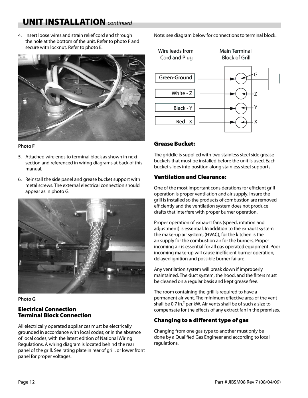
Note: see diagram below for connections to terminal block.
Wire leads from Cord and Plug
White - Z
Black - Y
Red - X
Main Terminal
Block of Grill
![]() G
G
Z
Y
X
Photo F
5.Attached wire ends to terminal block as shown in next section and referenced in wiring diagrams at back of this manual.
6.Reinstall the side panel and grease bucket support with metal screws. The external electrical connection should appear as in photo G.
Photo G
Electrical Connection
Terminal Block Connection
All electrically operated appliances must be electrically grounded in accordance with local codes; or in the absence of local codes, with the latest edition of National Wiring Regulations. A wiring diagram is located behind the rear panel of the grill. See rating plate in rear of grill, or lower front panel for proper voltages.
Grease Bucket:
The griddle is supplied with two stainless steel side grease buckets that must be installed before the unit is used. Each bucket slides into position along stainless steel supports.
Ventilation and Clearance:
One of the most important considerations for efficient grill operation is proper ventilation and air supply. Insure the grill is installed so the products of combustion are removed efficiently and the ventilation system does not produce drafts that interfere with proper burner operation.
Proper operation of exhaust fans (speed, rotation and adjustment) is essential. In addition to the exhaust system the
air supply for the combustion air for the burners. Proper incoming air is essential for all gas operated equipment. Poor incoming
Any ventilation system will break down if improperly maintained. The duct system, the hood, and the filters must be cleaned on a regular basis and kept grease free.
The room containing the grill is required to have a permanent air vent. The minimum effective area of the vent shall be 0.7 in.² per kW. Air vents shall be of such a size to compensate for the effects of any extract fan in the premises.
Changing to a different type of gas
Changing from one gas type to another must only be done by a Qualified Gas Engineer and according to local regulations.
Page 12 | Part # JIBSM08 Rev 7 (08/04/09) |