Installation
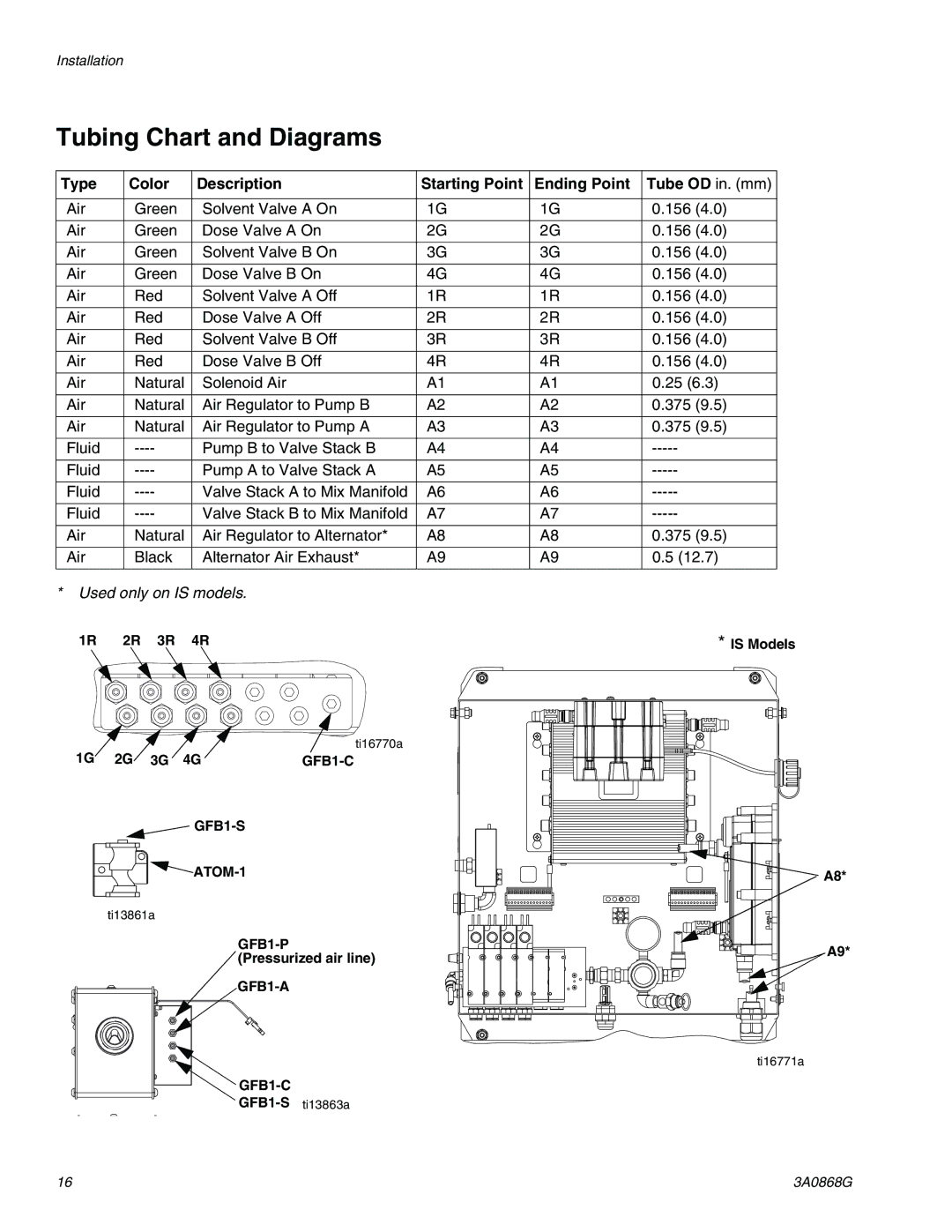
Tubing Chart and Diagrams
Type | Color | Description | Starting Point | Ending Point | Tube OD in. (mm) |
|
|
|
|
|
|
Air | Green | Solvent Valve A On | 1G | 1G | 0.156 (4.0) |
|
|
|
|
|
|
Air | Green | Dose Valve A On | 2G | 2G | 0.156 (4.0) |
|
|
|
|
|
|
Air | Green | Solvent Valve B On | 3G | 3G | 0.156 (4.0) |
|
|
|
|
|
|
Air | Green | Dose Valve B On | 4G | 4G | 0.156 (4.0) |
|
|
|
|
|
|
Air | Red | Solvent Valve A Off | 1R | 1R | 0.156 (4.0) |
|
|
|
|
|
|
Air | Red | Dose Valve A Off | 2R | 2R | 0.156 (4.0) |
|
|
|
|
|
|
Air | Red | Solvent Valve B Off | 3R | 3R | 0.156 (4.0) |
|
|
|
|
|
|
Air | Red | Dose Valve B Off | 4R | 4R | 0.156 (4.0) |
|
|
|
|
|
|
Air | Natural | Solenoid Air | A1 | A1 | 0.25 (6.3) |
|
|
|
|
|
|
Air | Natural | Air Regulator to Pump B | A2 | A2 | 0.375 (9.5) |
|
|
|
|
|
|
Air | Natural | Air Regulator to Pump A | A3 | A3 | 0.375 (9.5) |
|
|
|
|
|
|
Fluid | Pump B to Valve Stack B | A4 | A4 | ||
|
|
|
|
|
|
Fluid | Pump A to Valve Stack A | A5 | A5 | ||
|
|
|
|
|
|
Fluid | Valve Stack A to Mix Manifold | A6 | A6 | ||
|
|
|
|
|
|
Fluid | Valve Stack B to Mix Manifold | A7 | A7 | ||
|
|
|
|
|
|
Air | Natural | Air Regulator to Alternator* | A8 | A8 | 0.375 (9.5) |
|
|
|
|
|
|
Air | Black | Alternator Air Exhaust* | A9 | A9 | 0.5 (12.7) |
|
|
|
|
|
|
*Used only on IS models.
1R 2R 3R 4R | * IS Models |
1G 2G 3G 4G | ti16770a |
| |
A8* |
ti13861a |
| |
A9* | ||
(Pressurized air line) | ||
| ||
|
ti16771a
16 | 3A0868G |