Basic Operation
10.After the volume for A or B is entered, the ProMix 2KE controller calculates the new pump factor and shows it on Calibration 1 (Screen 22) and Calibra- tion 2 (Screen 23).
11.Before you begin production, clear the system of solvent and prime it with material.
a.Go to Mix mode.
b.Trigger the gun into a grounded metal pail until mixed material flows from the gun nozzle.
If the fluid flow rate is too low: increase air pres- sure to component A and B fluid supplies or increase the regulated fluid pressure of mixed material.
If the fluid flow rate is too high: reduce the air pressure to component A and B fluid supplies, close the dose valves further, or decrease the reg- ulated fluid pressure of mixed material.
4.Turn on atomizing air to the gun. Check the spray pattern as instructed in your spray gun manual.
Spraying |
| NOTE: | ||
|
| |||
NOTE: See Run Mode Details, pages | • Pressure adjustments of each component will | |||
vary with fluid viscosity. Start with the same fluid | ||||
screen information, if needed. | ||||
pressure for component A and B, then adjust as | ||||
|
|
| ||
|
|
| needed. | |
|
|
| • Do not use the first | |
|
|
| material as it may not be thoroughly mixed due | |
1. Calibrate the pumps as described in Pump Calibra- | to errors while priming the system. | |||
| ||||
| tion, page 31. Pump factors will update automati- | NOTICE | ||
| cally based on calibration results. Make additional | |||
| Do not allow a fluid supply tank to run empty. It is pos- | |||
| manual changes, if desired, as described in Cali- | |||
| bration 1 and 2 (Screens 22 and 23), page 46. | sible for air flow in the supply line to turn gear meters | ||
| Adjust the flow rate. | in the same manner as fluid. This can damage the | ||
| meters and lead to the proportioning of fluid and air | |||
|
|
| ||
|
|
| that meets the ratio and tolerance settings of the | |
2. | Press | . The system will load the correct potlife | equipment. This can further result in spraying | |
| volume based on hose length and diameter entered | uncatalyzed or poorly catalyzed material. | ||
|
| |||
| on Configure 2 (Screen 19). Once material is |
| ||
loaded, the system returns to Standby. Press ![]() again to spray the loaded recipe.
again to spray the loaded recipe.
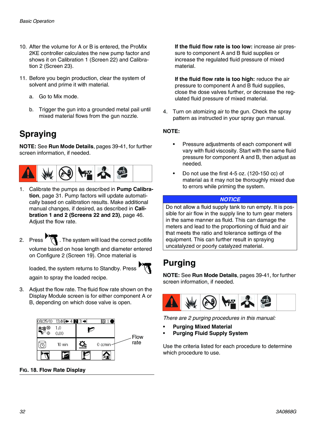
3.Adjust the flow rate. The fluid flow rate shown on the Display Module screen is for either component A or B, depending on which dose valve is open.
Flow rate
Purging
NOTE: See Run Mode Details, pages
There are 2 purging procedures in this manual:
•Purging Mixed Material
•Purging Fluid Supply System
Use the criteria listed for each procedure to determine which procedure to use.
FIG. 18. Flow Rate Display
32 | 3A0868G |