Manuals
/
Graco
/
Power Tools
/
Power Roller
Graco
3A0868G
important safety instructions
Pump Control, Home, Run, Errors, Mix
Models:
3A0868G
1
25
74
74
Download
74 pages
34.71 Kb
22
23
24
25
26
27
28
29
Troubleshooting
Install
Error messages
Tubing Chart and Diagrams
System Alarms
Password
Errors
Warranty
Dimension
Maintenance
Page 25
Image 25
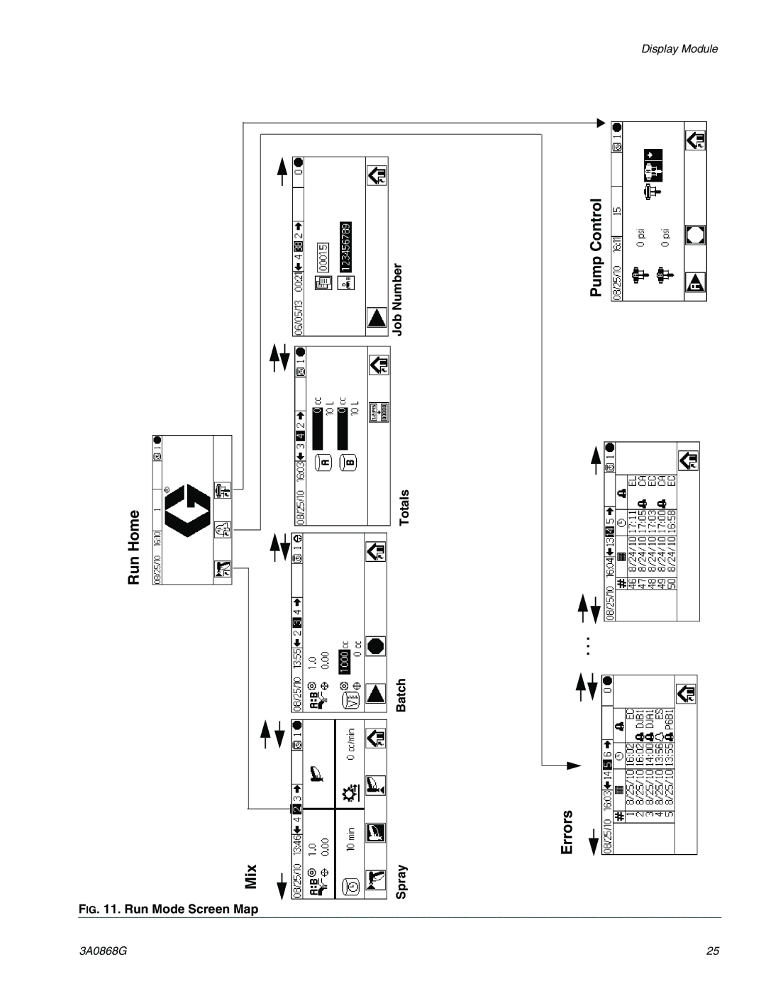
Display Module
Number
Pump Control
Job
Home
Totals
Run
.
.
.
Batch
Errors
Mix
Spray
F
IG
. 11. Run Mode Screen Map
3A0868G
25
Page 24
Page 26
Page 25
Image 25
Page 24
Page 26
Contents
ProMix 2KE
Contents
USB
Models
Series Ratio Pumps Psi MPa, bar Port Approvals
Models
Related Manuals
Manual Description
Special Conditions for Safe USE
Fire and Explosion Hazard
Electric Shock Hazard
Skin Injection Hazard
Intrinsic Safety
Moving Parts Hazard
Equipment Misuse Hazard
Toxic Fluid or Fumes Hazard
Personal Protective Equipment
Important Two-Component Material Information
Glossary of Terms
Overview
Installation
Usage
Component Identification and Definition
Hazardous Location Installation
Intrinsically Safe Installation Requirements
Non-Hazardous Locations
Air Supply
Display Module
Requirements
Air regulator and bleed-type shutoff valve
Air Connections
Fluid Supply
Fluid Connections
Key
SVA DVA
SVB DVB
Used only on is models
Tubing Chart and Diagrams
GFB1-A ATOM-1 ATOM-2
Electrical
Power Connection non-IS units only
Grounding
Grounding
Display
Display Module
IG . Display Module
Key Function
Icon Key
Setup Mode
Run Mode
Troubleshooting
Screen Summary
Ranges for User Inputs
Screen User Input Range/Options Default
Pump Control
Errors
Home
Run
Recipe
Set-Up Home Password Configure
Calibration Set-Up Home
Maintenance
System Outputs
System Outputs Set-Up Home System Inputs
Membrane Test
Initial System Setup
Power On
Basic Operation
Pre-Operation Tasks
Prime the System
Calibrate the pump
Pump Calibration
Purging
Spraying
Bration 1 and 2 Screens 22 and 23,
Purging Mixed Material Purging Fluid Supply System
Purging Fluid Supply System
Purging Mixed Material
Solenoid Valves in Control Box
Valve Settings
Pressure Relief Procedure
Lock Mode
Shutdown
Use of Optional USB Module
Error Log
USB Logs
Job Log
Sample Error Log
Setup
Recommended USB Flash Drives
Download Procedure
USB Port
Run Mix Spray Screen
Run Mode Details
Run Home Screen
Run Mix Batch Screen
Run Mix Totals Screen
Run Log Errors Screens
Run Job Number Screen
Run Pump Control Screen
Run Pump Control Screen
Password Screen
Setup Mode Details
Setup Home Screen
Confirm Change of System Type
Configure 1-4 Screens
Recipe 1-1 Screen Recipe 1-2 Screen
Configure 3 Screen 20 and Configure 4 Screen
Maintenance Recommendations
Maintenance 1-3 Screens
Recommended Maintenance
Component Frequency
Calibration 1 and 2 Screens 22
Troubleshooting Screens
Troubleshooting System Outputs Screen
Troubleshooting System Inputs Screen
Membrane Test Screen
General Operating Cycle, Dynamic Dosing
Dynamic Dosing
Select a Component B Restrictor Size
B Control Range with Properly Sized Restrictor
Pressure Too High Pressure Too Low Pressure B Pressure
System Alarms
System Errors
To Clear Error and Restart
Air Flow Switch AFS Function
System Idle Warning Idle
System Alarm/Advisory/Record Codes
Error Codes
Alarm and Description Cause Solution
Alarm Troubleshooting
Communication Error
USB Communication Error
EQU2
PreMix Error
Alarm and Description Cause Solution SFA1 or SFB1
Pneumatic Schematic, page 66 or
PreFill Error
Already about equal, verify that com
Ratio Low Error
QDB1
QDA1
Dose Time Error
Alarm and Description Cause Solution QTA1 or QTB1
Leak Error
Linear Sensor Error
Diving/Cavitation Error
Alarm and Description Cause Solution DDA1 or DDB1
Park Error
Stall Up Error
Example
Dynamic Dosing Restrictor Selection Graphs
Restrictor Sizes Size Code Orifice Size
Flow Rate cc/min Detail View
Differential Pressure between a and B
500 1000 1500 2000 2500 3000 3500 4000
200 14 150 10 100 7 50 3.4 500 1000
Psi
40 2.8 30 2.1 20 1.4 10 0.7 500 1000
System Pneumatic Schematic
Schematics
Non-Hazardous Location
Pneumatic Schematic
AIR Flow Switch SIG
Fluid J4CONTROL Module
Hazardous Location Electrical Schematic
Power Supply
Non-Hazardous Electrical Schematic
Merkur Merkur Bellows
Dimensions and Mounting
ProMix 2KE Metric
Technical Data
On-ratio accuracy
Noise level
Graco Information
Graco Standard Warranty
Top
Page
Image
Contents