313314B
Consignes DE Sécurité Importantes
Grounding Instructions
Grounding
Fire and Explosion Hazard
Skin Injection Hazard
Equipment Misuse Hazard
Electric Shock Hazard
Pressurized Aluminum Parts Hazard
Moving Parts Hazard
Mise en garde
Instructions de mise à la terre
Mise a LA Terre
Mise EN Garde
Risques DUS AUX Pièces EN Aluminium Sous Pression
Équipement DE Protection Personnelle
Advertencias
Instrucciones de conexión a tierra
Peligro DE Incendios Y Explosiones
De los vapores explosivos
Peligros Debidos a LA Utilización Incorrecta DEL Equipo
Lesiones graves y daños materiales
English Français Español
Filtre Filtro
Fluid Outlet
English
Français
Español
Ou de court-circuit Haya un cortocircuito
Power Requirements
Extension Cords
Spécification électrique
Rallonges
Pails
Bidones
Tierra. Después dispare la pistola
Pressure Relief
Décompression
Descompresión
Setup / Installation / Puesta en marcha
Al pulverizador. Apriete firmemente
Revise el elemento filtrante de entrada
Turn prime valve down
’huile et l’huile d’entreposage
Turn power on
La gâchette du pistolet
Coloque el tubo de aspiración en la lata de pintura
Ti13023a
Spray
Clear Clog
Never point gun at your hand or into a rag
Pulvériser
Perform Pressure Relief
Position
’écoule
15 to 30 seconds to drain fluid
Turn prime valve down Drain position. Unplug sprayer
Secondes pour nettoyer le tuyau de vidange
Ouvrir la vanne d’amorçage. Débrancher Le pulvérisateur
Ti2895a Ti13029a
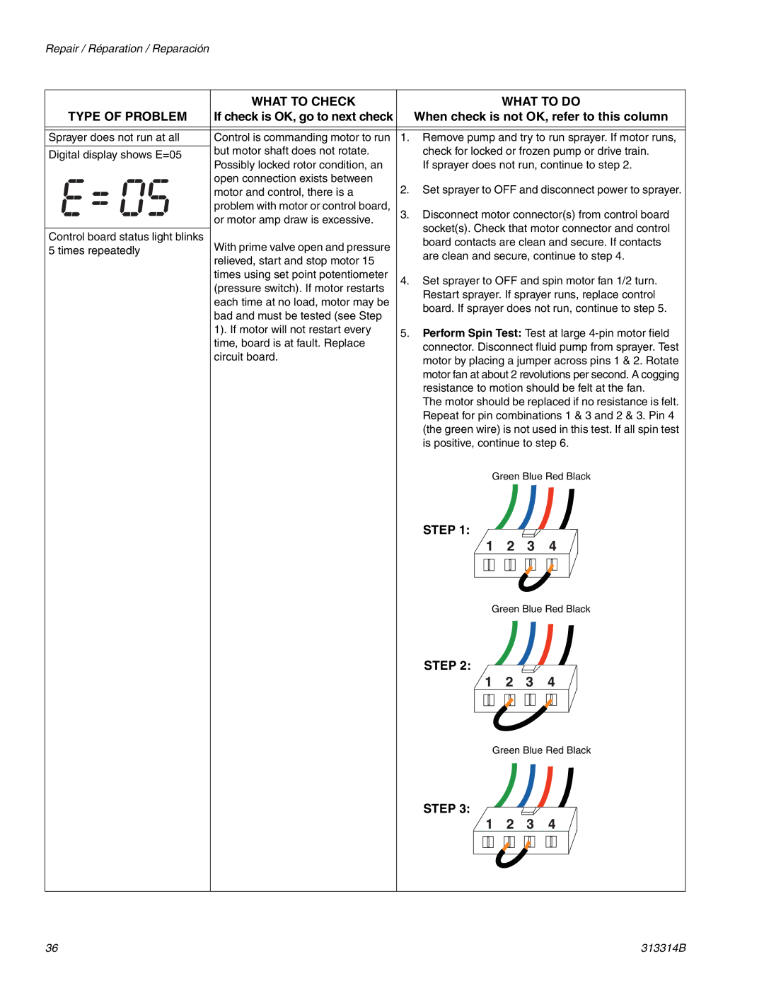
What to Check What to do Type of Problem
Repair / Réparation / Reparación
With heavy materials
Hose significantly reduces performance
Sprayer. Use 3/8 in. hose for optimum
Performance 50 ft minimum
Quoi Vérifier Quoi Faire
Type DE Problème
Consulter cette colonne
Aller à la vérification suivante
Aller à la vérification suivante Consulter cette colonne
Problema
Causa Medida a Tomar
De las siguientes causas Consulte esta columna
Compruebe si existe alguna Cuando detecte la causa
En la tuerca prensaestopas Está floja
Limpie la boquilla consulte el manual
Del protector de la boquilla
Electrical
Électricité
Problemas eléctricos
Instrucciones para observar los códigos de error
Avertissement
Alivie la presión, página
Electrical Troubleshooting
If check is OK, go to next check
Detecting a pressure signal
Contacts are clean and secure
Sprayer does not run at all Check transducer or transducer
Connections control board is not Digital display shows E=03
Step
Check Motor Thermal Switch Unplug thermal
Resistance Table
Reconnect thermal device connector to control
Board socket. Connect power, turn sprayer on
Secure
Is not correct, replace motor
Troubleshooting Procedure
Electric Motor Will Not Shut Off
YES
Motor Will Not Run
See . Do You have over AC volts?
Defective thermal device Connect a test
Replace
Control Board With GFI Filter Coil
Dépannage électrique
Si tout est normal après
Suivante Consulter cette colonne
Quoi Vérifier
Étape
Faire l’Essai de rotation essai au gros connecteur
Tableau des résistances
Faire l’Essai de court-circuitage de champ essai au
Aucun fonctionnement Laisser le pulvérisateur se refroidir
Remplacer le bloc de commande
Arrêt impossible du moteur
Procédure de dépannage
NON
Refus du moteur de tourner
OUI NON
Remplacer ’interrupteur Si le moteur est chaud, laisser
Remplacer le
Fil blanc du cordon d’alimentation
Solución de problemas eléctricos
Consulte esta columna
Causa Medida a Tomar
Paso
Realice una prueba de rotación Someta a una prueba
Tabla de resistencia
Realice una prueba breve de campo Someta a una
Inspeccione el interruptor térmico del motor
Procedimiento de solución de problemas
El motor elétrico no se apaga
El motor no funciona
Repare
Cambie el Interruptor de alimentación
Motor? Cambie el Tablero de
Negro al tablero Negro desde el cable eléctrico
Removal / Retrait / Extracción
Front Shroud
Carénage avant
Recubrimiento delantero
Installation / Installation / Instalación
Front Shroud Rear Shroud
Carénage avant Carénage arrière
Recubrimiento delantero Recubrimiento trasero
Diagram,
Connectors
Disconnect transducer 86 and remove wiring grommet
Quite el tornillo de la puesta a tierra 26 y el cable
Quite el ojal y desconecte
Ti13083a
Ti13083a Ti13084a Ti12999a Ti13087a
Installer le fil de terre et serrer la vis
Replace shroud 58 and tighten screws 13
Remettre en place le carénage 58 et serrer les vis 13 et
115
Quite la cubierta trasera página
Rotate new potentiometer
Ti13074a Ti12999a
86G
Replace transducer wiring
Use wrench to tighten Wiring protector Grommet 86G
Remettre en place
Brancher le fil du transducteur Remettre en place
Remettre en place Les carénages avant et arrière, voir
Avis
Motor
Replace pump, Lift retaining spring and replace pump pin
Replace pump rod covers Replace front shroud Tighten screws
Replace rear shroud,
Power cord
Flush pump Remove screws 31
Push up retaining spring Push pump pin 44 out
Débrancher le flexible
Installation / Installation / Instalación
Étendre la tige de piston de la pompe sur 1,5 po
Extienda la varilla del pistón 1.5 in. Aplique grasa
De bombeo en o dentro de la varilla de unión
De la bomba se enganche
102 Nm
Visser l’écrou de blocage
± 5 lb-pi 102 Nm
Arrière, voir
Replace rear shroud mounting bracket 49. Replace shroud,
Vuelva a colocar el Alojamiento del
Rodamiento Del recubrimiento Página
Colocar el
Parts / Pièces / Piezas
Ref. Part Description
Part Description Qty
Qty
Screw
Parts Filter / Pièces Filtre / Piezas Filtro
Wiring Diagram
Diagramme de câblage
Diagrama de cableado
Interruptor Thermal Térmico Switch Potenciómetro
Motor
Transductor
Technical Data
Fiche technique
Datos técnicos
Warranty / Garantie / Garantía
Graco Headquarters Minneapolis
International Offices Belgium, Korea, China, Japan
11/2008

