B. Securing and Leveling the Appliance
WARNING! Risk of Fire! Prevent contact with:
•Sagging or loose insulation
•Insulation backing or plastic
•Framing and other combustible materials
Block openings into the chase to prevent entry of blown- in insulation. Make sure insulation and other materials are secured.
DO NOT notch the framing around the appliance standoffs. Failure to maintain air space clearance may cause overheating and fire.
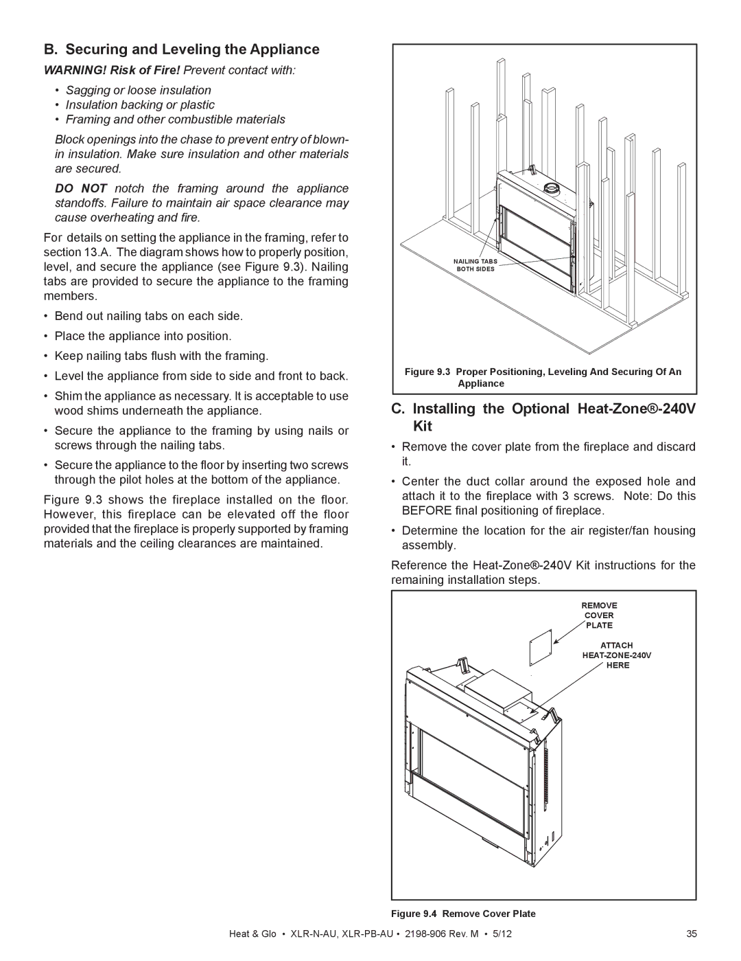
For details on setting the appliance in the framing, refer to section 13.A. The diagram shows how to properly position, level, and secure the appliance (see Figure 9.3). Nailing tabs are provided to secure the appliance to the framing members.
•Bend out nailing tabs on each side.
•Place the appliance into position.
•Keep nailing tabs flush with the framing.
•Level the appliance from side to side and front to back.
•Shim the appliance as necessary. It is acceptable to use wood shims underneath the appliance.
•Secure the appliance to the framing by using nails or screws through the nailing tabs.
•Secure the appliance to the floor by inserting two screws through the pilot holes at the bottom of the appliance.
Figure 9.3 shows the fireplace installed on the floor. However, this fireplace can be elevated off the floor provided that the fireplace is properly supported by framing materials and the ceiling clearances are maintained.
NAILING TABS |
BOTH SIDES |
Figure 9.3 Proper Positioning, Leveling And Securing Of An |
Appliance |
C. Installing the Optional Heat-Zone®-240V Kit
•Remove the cover plate from the fireplace and discard it.
•Center the duct collar around the exposed hole and attach it to the fireplace with 3 screws. Note: Do this BEFORE final positioning of fireplace.
•Determine the location for the air register/fan housing assembly.
Reference the
REMOVE |
COVER |
PLATE |
ATTACH |
HERE |
Figure 9.4 Remove Cover Plate
Heat & Glo • | 35 |