5K320 SATA OEM Specification
7 Electrical interface specifications
7.1Cabling
The maximum cable length from the host system to the hard disk drive plus circuit pattern length in the host system shall not exceed 1 meter.
7.2Interface connector
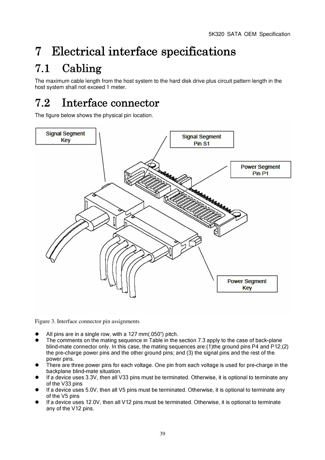
The figure below shows the physical pin location.
Figure 3. Interface connector pin assignments
All pins are in a single row, with a 127 mm(.050”) pitch.
The comments on the mating sequence in Table in the section 7.3 apply to the case of
There are three power pins for each voltage. One pin from each voltage is used for
If a device uses 3.3V, then all V33 pins must be terminated. Otherwise, it is optional to terminate any of the V33 pins
If a device uses 5.0V, then all V5 pins must be terminated. Otherwise, it is optional to terminate any of the V5 pins
If a device uses 12.0V, then all V12 pins must be terminated. Otherwise, it is optional to terminate any of the V12 pins.
39