5K320 SATA OEM Specification
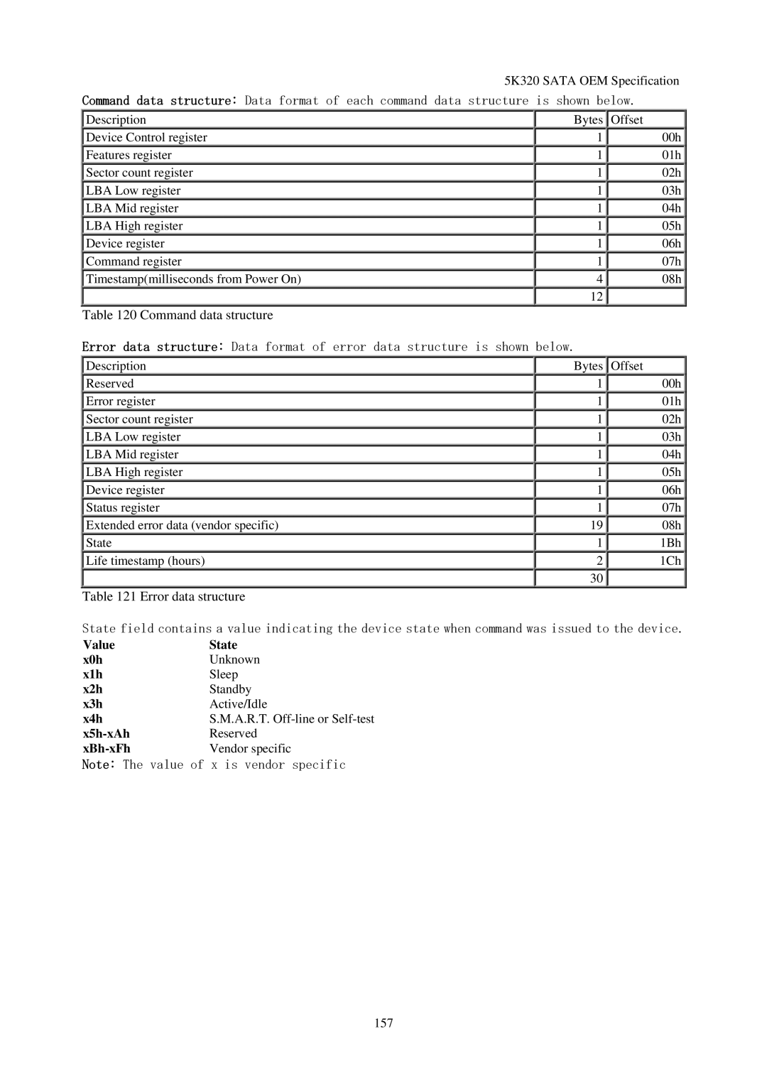
Command data structure: Data format of each command data structure is shown below.
Description
Device Control register
Features register
Sector count register
LBA Low register
LBA Mid register
LBA High register
Device register
Command register
Timestamp(milliseconds from Power On)
Table 120 Command data structure
Bytes | Offset |
1 | 00h |
1 | 01h |
1 | 02h |
1 | 03h |
1 | 04h |
1 | 05h |
1 | 06h |
1 | 07h |
4 | 08h |
12 |
|
Error data structure: Data format of error data structure is shown below.
Description
Reserved
Error register
Sector count register
LBA Low register
LBA Mid register
LBA High register
Device register
Status register
Extended error data (vendor specific)
State
Life timestamp (hours)
Table 121 Error data structure
Bytes | Offset |
1 | 00h |
1 | 01h |
1 | 02h |
1 | 03h |
1 | 04h |
1 | 05h |
1 | 06h |
1 | 07h |
19 | 08h |
1 | 1Bh |
2 | 1Ch |
30 |
|
State field contains a value indicating the device state when command was issued to the device.
Value | State |
x0h | Unknown |
x1h | Sleep |
x2h | Standby |
x3h | Active/Idle |
x4h | S.M.A.R.T. |
| Reserved |
| Vendor specific |
Note: The value of x is vendor specific
157
