Hardware Installations
2-2 LED Indicators
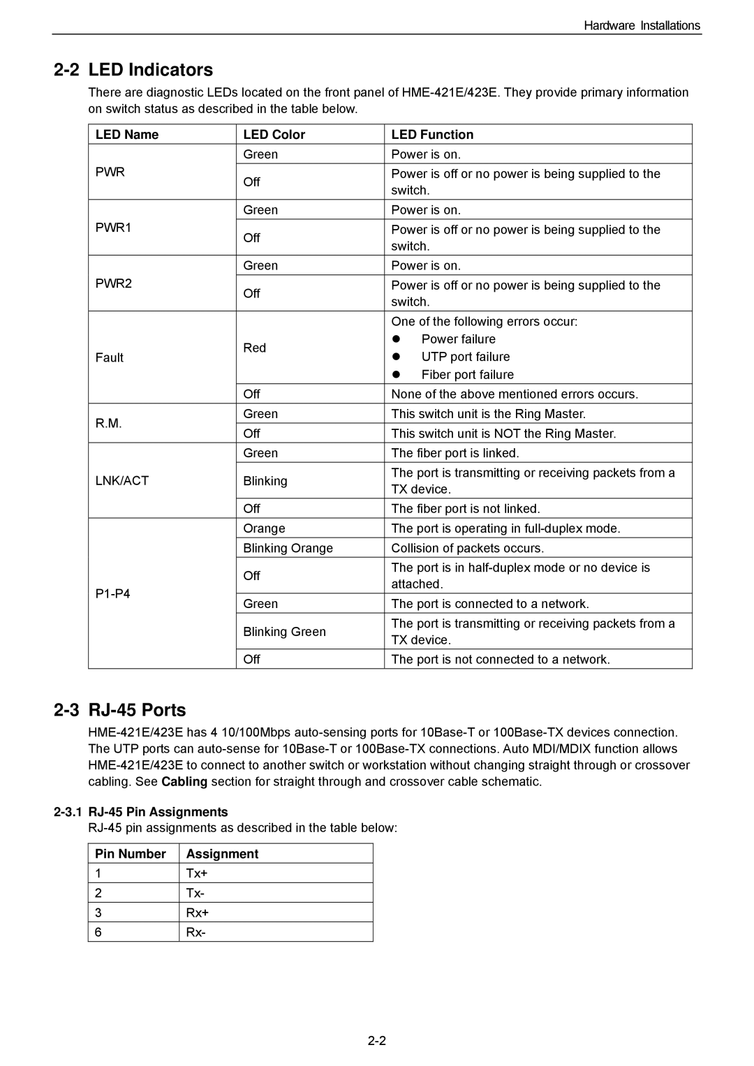
There are diagnostic LEDs located on the front panel of
LED Name | LED Color | LED Function | ||
| Green | Power is on. | ||
PWR | Off | Power is off or no power is being supplied to the | ||
| switch. | |||
|
| |||
| Green | Power is on. | ||
PWR1 | Off | Power is off or no power is being supplied to the | ||
| switch. | |||
|
| |||
| Green | Power is on. | ||
PWR2 | Off | Power is off or no power is being supplied to the | ||
| switch. | |||
|
| |||
|
| One of the following errors occur: | ||
| Red | z | Power failure | |
Fault | z | UTP port failure | ||
| ||||
|
| z | Fiber port failure | |
| Off | None of the above mentioned errors occurs. | ||
R.M. | Green | This switch unit is the Ring Master. | ||
Off | This switch unit is NOT the Ring Master. | |||
| ||||
| Green | The fiber port is linked. | ||
LNK/ACT | Blinking | The port is transmitting or receiving packets from a | ||
TX device. | ||||
|
| |||
| Off | The fiber port is not linked. | ||
| Orange | The port is operating in | ||
| Blinking Orange | Collision of packets occurs. | ||
| Off | The port is in | ||
| attached. | |||
| ||||
Green | The port is connected to a network. | |||
| ||||
| Blinking Green | The port is transmitting or receiving packets from a | ||
| TX device. | |||
|
| |||
| Off | The port is not connected to a network. | ||
2-3 RJ-45 Ports
2-3.1 RJ-45 Pin Assignments
Pin Number | Assignment |
1 | Tx+ |
2 | Tx- |
3 | Rx+ |
6 | Rx- |
